20 Bar super quench vacuum furnace

a vacuum furnace and super-quench technology, applied in the direction of furnaces, muffle furnaces, heat treatment equipment, etc., can solve the problems of reducing affecting the heat transfer efficiency of the furnace, etc., to achieve the effect of improving the heat transfer efficiency

Active Publication Date: 2014-02-13
JONES WILLIAM R
View PDF3 Cites 14 Cited by
  • Summary
  • Abstract
  • Description
  • Claims
  • Application Information

AI Technical Summary

Benefits of technology

[0010]This invention is related to a single chamber vacuum heat treating furnace in which a work piece is heat treated and gas quenched in the same chamber,

Problems solved by technology

However, it is rife with disadvantages, such as cracking and distortion due to high residual stress on the processed material.
Some tool steel grades with reasonable cross-sections have been successfully quenched in a 10 Bar vacuum furnace, but there are limitations of the load size and part dimensions which need to be overcome.
The use of 10 Bar quenching for lower alloy tool steels is limited.
Typical gas flow designs have stationary exit ports, which result in restricted gas flow and unacceptable pressure drops.
These passageways result in high pressure drops, which are fine for an atmosphere quench design, but detrimental for quench pressures up to 20 Bar.
Prior art references—U.S. Pat. Nos. 4,836,776, 4,906,182 and 5,478,985—teach improved gas fl

Method used


Image

  • 20 Bar super quench vacuum furnace
  • 20 Bar super quench vacuum furnace
  • 20 Bar super quench vacuum furnace

Examples


Embodiment Construction

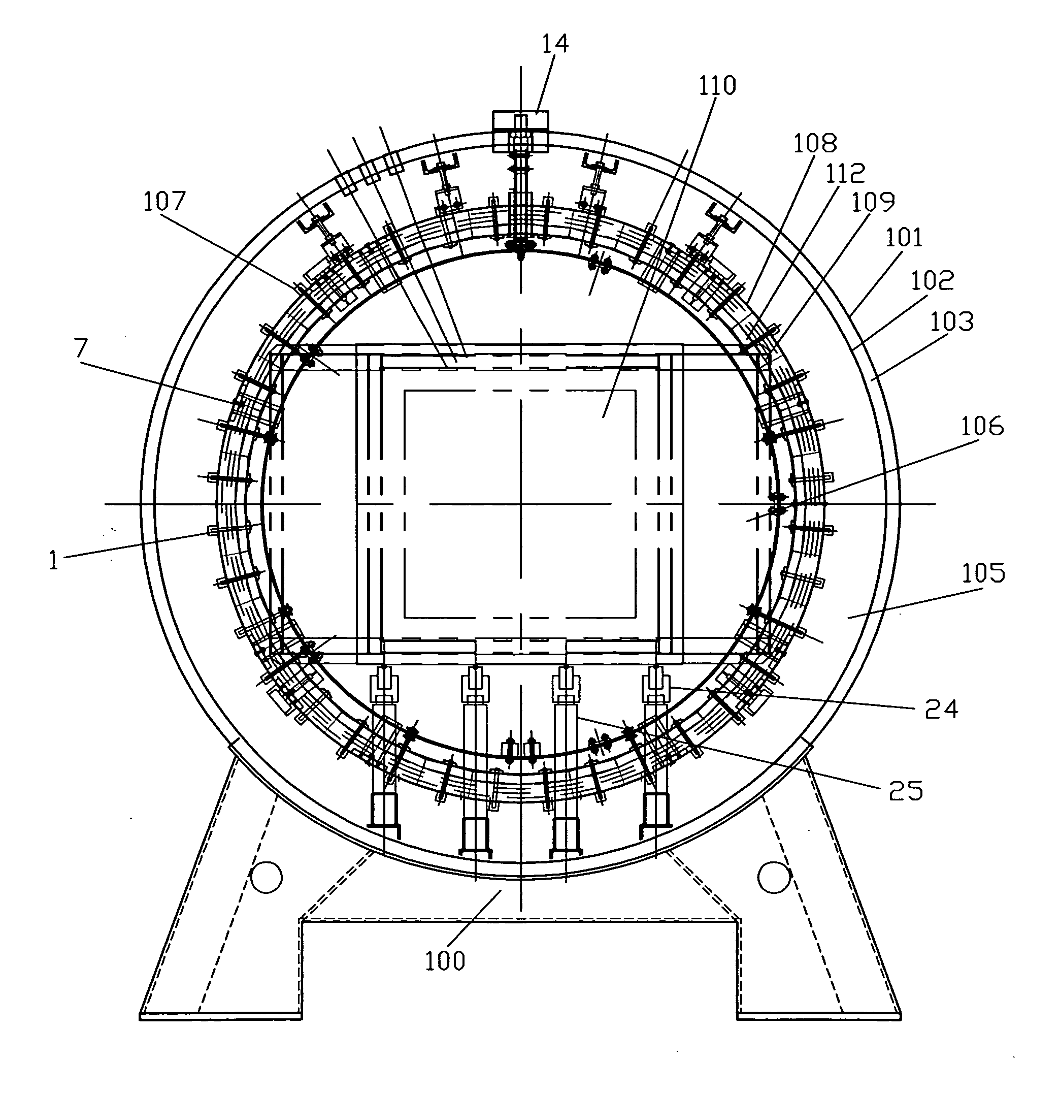
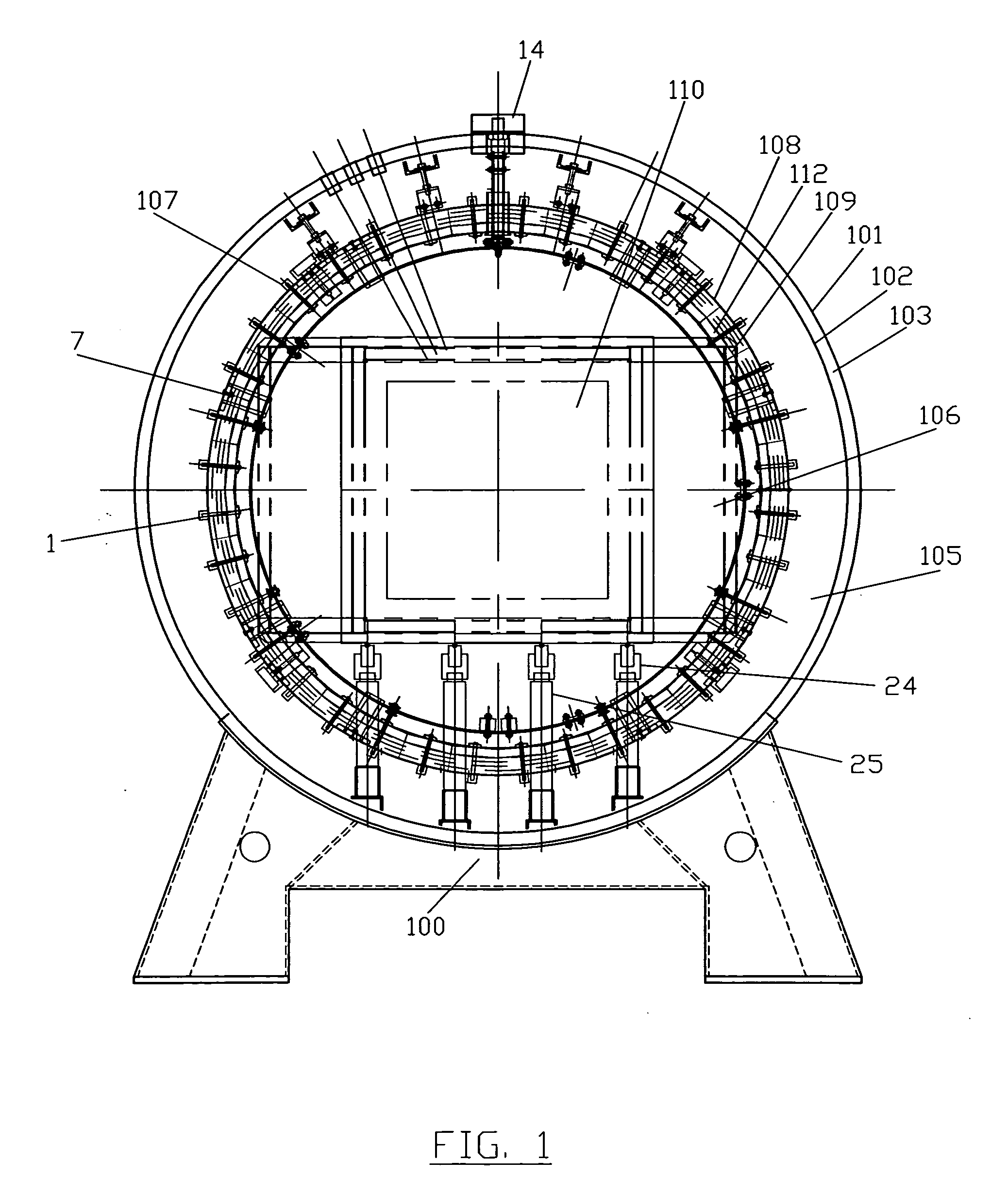
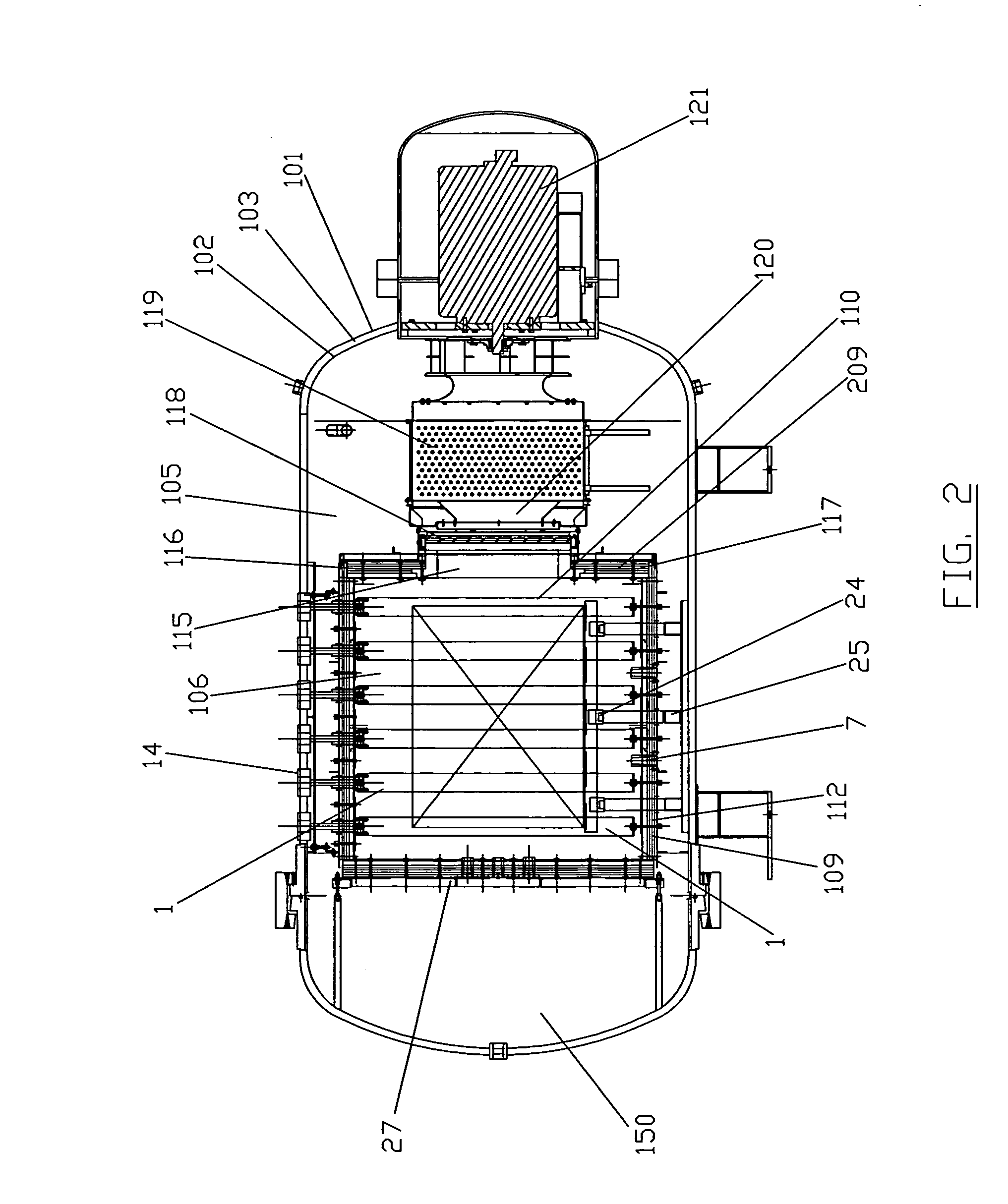
[0016]Referring to the drawings wherein like reference numerals refer to the same or similar elements across the multiple views, FIG. 1 depicts a partial front open door cross-section view (looking toward the door end) of a high temperature vacuum-high pressure quench heat treating furnace 100. Furnace 100 includes a hinged door 150 (shown in FIG. 2) which is opened to allow the insertion of a work piece to be heat treated, and then closed during the heat treating cycle. Outer furnace wall 101 and inner wall 102 of furnace 100 form the radial boundaries of a furnace water jacket 103 used for cooling outer wall 101 of the furnace. The outer chamber of furnace 100 thus is a cylindrical double walled, water-cooled vessel, and is typically manufactured from low carbon steel. All flanges are similarly machined. The width of water jacket 103 is approximately 1 inch maximum, with large oversized water inlet and exit ports (not shown) located around the chamber to allow for convenient perio...


PUM

PropertyMeasurementUnit
Velocityaaaaaaaaaa
Temperatureaaaaaaaaaa
Pressureaaaaaaaaaa

Abstract

A vacuum furnace for heat treating and rapid gas quenching insitu a work piece at pressures up to 20 Bar and high gas velocities. The furnace comprises a single chamber having an inner portion including a plurality of graphite heating elements and graphite insulation, an outer portion and an access door. Further included are movable radiation baffle doors. In their closed position hot gases heat treat the work piece. In their open position the hot gases escape through the opening created onto chevron-shaped baffles in the outer portion which reflect radiation heat energy back into the inner portion and diffuse only convective heat energy into a heat exchanger and a variable speed drive recirculating fan. The recirculating fan directs the cooling gases through cooling nozzles onto the work piece to quench it to a pre-programmed temperature.

Description

BACKGROUND OF THE INVENTION[0001]1. Field of the Invention[0002]The present invention relates to a horizontal, single chamber front loading vacuum heat treating furnace capable of rapidly cooling the heat treated materials by insitu gas quenching at pressures up to 20 Bar and gas velocities approaching 200 miles / hour in a single chamber of the furnace.[0003]2. Description of the Prior Art[0004]The need for “green” environmentally friendly quenching capabilities has challenged furnace engineers to design furnaces capable of achieving high pressure, rapid gas quenching up to 20 Bar or greater. The ability to achieve such high gas pressures for cooling is driven by the need to eliminate the use of oil quenching for cooling of tool steels. Oil quenching is currently the fastest quenching medium for heat treatment of tool steels. However, it is rife with disadvantages, such as cracking and distortion due to high residual stress on the processed material. Some tool steel grades with reaso...

Claims


Application Information

Patent Timeline
IPC IPC(8): C21D1/773C21D1/62
CPCC21D9/0043C21D1/773C21D9/0062
Inventor WILSON, ROBERT J.DALEY, ROBERT F.
Owner JONES WILLIAM R
Why Eureka
Try Eureka