Extendable Loop Antenna for Portable Communication Device

a portable communication device and loop antenna technology, applied in the field of wireless communication, can solve the problems of limiting the miniaturization of the electrical size of the antenna, reducing the efficiency of the antenna, and unable to achieve the efficient antenna for a relatively low frequency (i.e. long wavelength), and achieves low rf resistance, high efficiency, and large surface area

Inactive Publication Date: 2014-02-20
KATZ
View PDF11 Cites 9 Cited by
  • Summary
  • Abstract
  • Description
  • Claims
  • Application Information

AI Technical Summary

Benefits of technology

[0041]A hollow conductor, like a copper pipe or tube, is advantageously for having relatively a large surface, contributing to a low RF resistance considering the “skin effect”, and consequently high efficiency.
[0042]A...

Problems solved by technology

Ideally, a small and efficient antenna should be designed for most wireless devices, however, a well known rule trades off between these two parameters, limiting the miniaturization of the electrical size of an antenna, for a given efficiency.
Clearly, smaller than λ/4 antennas can be configured, yet this usually degrades the antenna efficiency.
Thus, an efficient antenna for a relatively low frequency (i.e. long wavelength) is not easily achieved in small dimensions.
As well known in the art, one of the disadvantages of ESAs is a narrow bandwidth, which is related to a high Q (quality factor).
Furthermore, in almost any practical environment an electrically small antenna is near some type of ground plane or other structure and not in free space.
Obviously, a narrow bandwidth is inconvenient.
Even if coupled to a wireless device configured to operate within this band, the antenna might still detune due to rain, snow, dust etc.
It is therefore not easy to design a small antenna (ESA), efficient and wide band, operating in the vicinity of a ground plane, particularly an antenna that radiates most of its energy horizontally, as many planar antennas do.
None of these teach planar radiating elements that move in parallel to a ground plane.
Yet, this method might be problematic since such a whip dipole antenna is quite long for VHF/UHF bands.
Still, the extended helical antenna is not robust enough to enable performing hard physical tasks su...

Method used


Image

  • Extendable Loop Antenna for Portable Communication Device
  • Extendable Loop Antenna for Portable Communication Device
  • Extendable Loop Antenna for Portable Communication Device

Examples


second embodiment

[0089]According to the present invention, said radiating element is made of a flat conductor configured in form of a loop.

third embodiment

[0090]According to the present invention, said radiating element is made of a solid conductor configured in form of a loop.

[0091]According to said first and second and third embodiments, the antenna is configured to operate in the band of 406.0-406.1 MHz (at least), which is the band allocated to the Cospas-Sarsat Search and Rescue (SAR) satellite system.

first embodiment

[0092]According to said first embodiment, the first radiating element is made of a hollow copper pipe with external diameter of 6 mm (¼ inch) and internal diameter of 4 mm, bent into a loop (circle) with an internal diameter of 50 mm. This loop is not closed, and a gap of about 2 mm is kept between its terminals, as shown in FIG. 3 (a).

[0093]FIG. 3 shows a Hollow Loop Radiating Element, according to the first embodiment of the present invention, in top view (a) and side view (b).

[0094]Further according to the first embodiment of the present invention, a capacitor of 1-3 pf is soldered between said loop terminals, as shown in FIG. 5.

[0095]Optionally, a resistor is placed in parallel to said capacitor to decrease the antenna quality factor (Q) and accordingly increase its band width, traded off for lower antenna efficiency.

[0096]According to said second embodiment, the first radiating element is made of a flat copper PCB trace with 6 mm of width, in form of a loop (circle) with an int...


PUM


Abstract

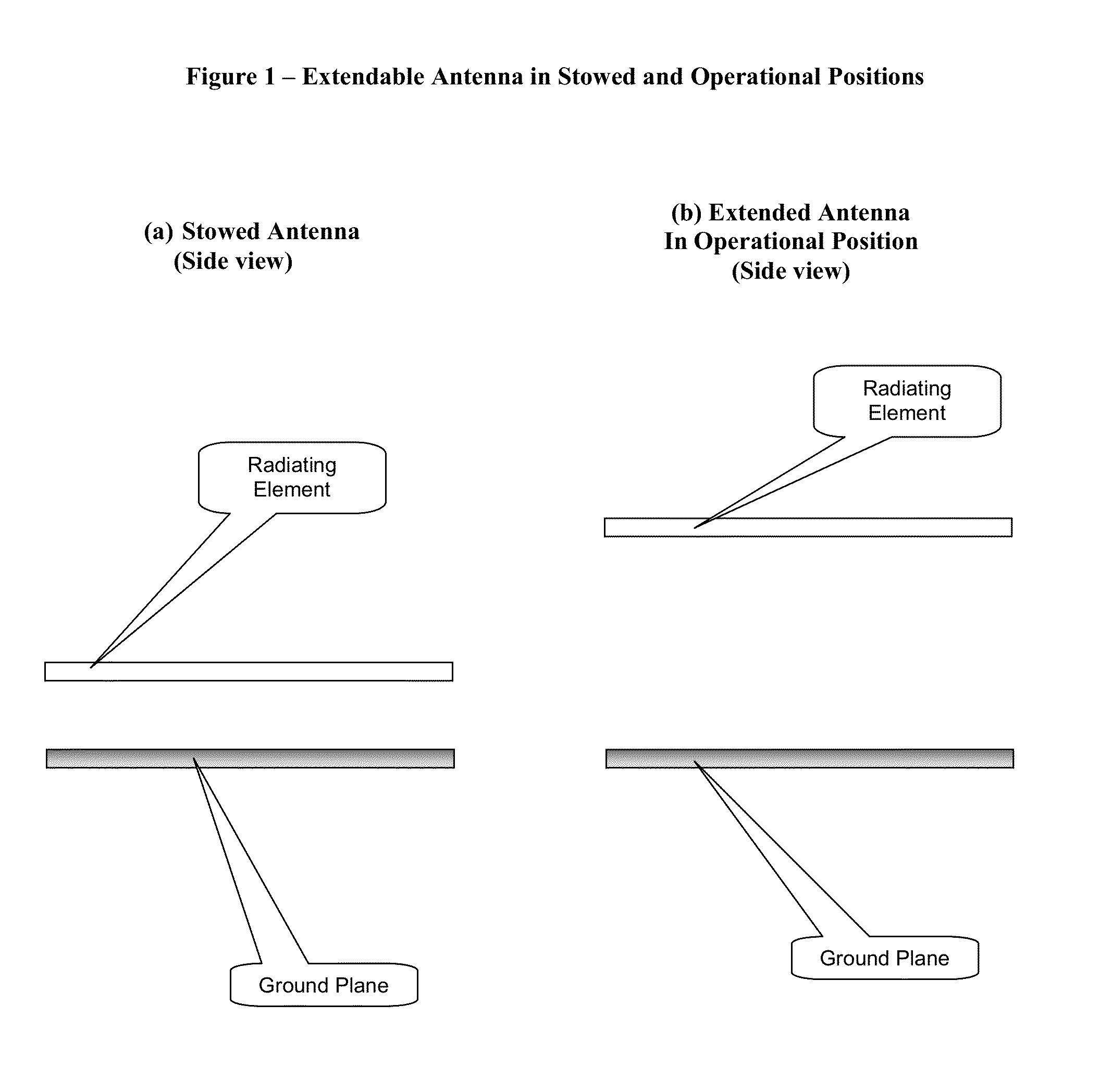
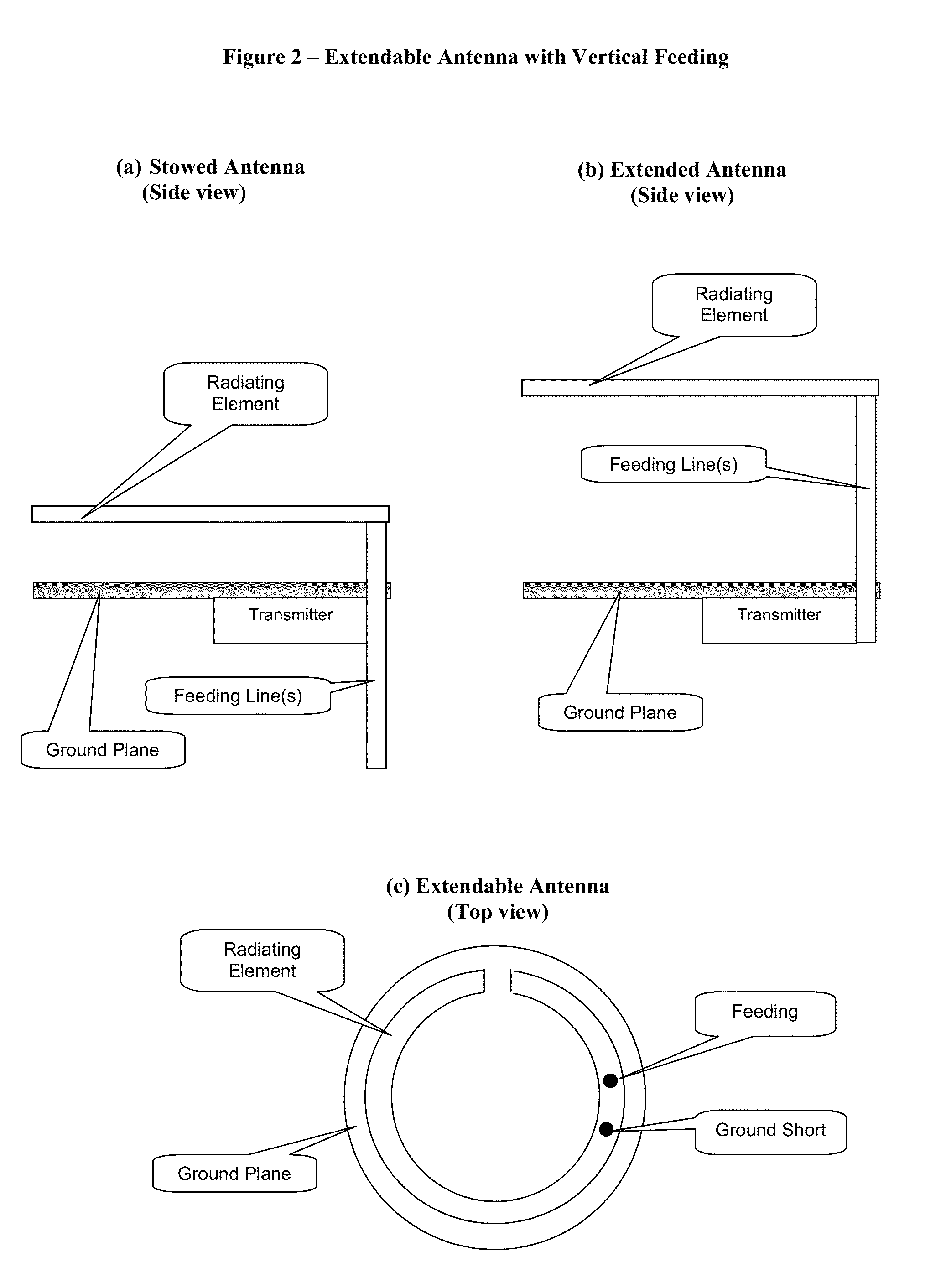
The present invention discloses a wireless communication device with an extendable planar antenna. The antenna is made of a radiating loop, and a ground plane, wherein the loop is parallel to the ground plane and the distance between the loop and the ground plane is configurable, attaining at least two positions: a stowed position where the loop is close to the ground plane, and an operational position where the loop moves apart from the ground plane, to improve the antenna radiation properties. According to one embodiment, this wireless device is a Personal Locator Beacon (PLB) for Search and Rescue (SAR) of people in distress, configured to be wrist worn.

Description

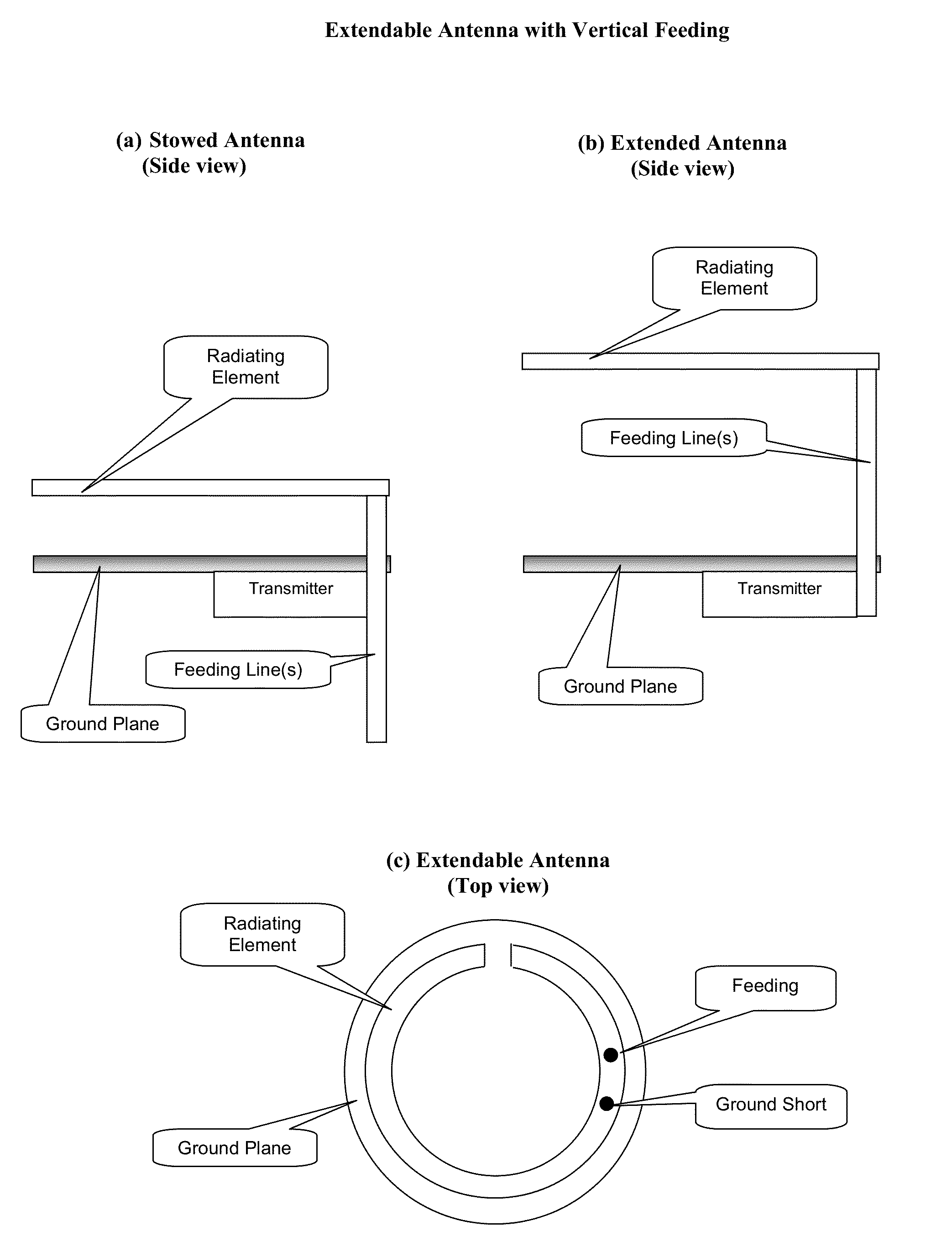
BACKGROUND OF THE INVENTION[0001]The present invention relates to wireless communications and particularly to Radio Wave Antennas.[0002]Efficiency of a transmitting antenna is usually defined as the ratio between the power the antenna radiates and the power put into the antenna by a coupled transmitter. Obviously, a high efficiency is usually desirable in an antenna.[0003]The physical size of an antenna, normalized to its operating wavelength, usually refers in the art as the “electrical size” of the antenna, so a “small antenna” usually (including in the present document) means an Electrically Small Antenna (ESA). Clearly, small antennas are desirable, particularly in mobile and portable devices.[0004]Ideally, a small and efficient antenna should be designed for most wireless devices, however, a well known rule trades off between these two parameters, limiting the miniaturization of the electrical size of an antenna, for a given efficiency. This rule also indicates that at least on...

Claims


Application Information

Patent Timeline
IPC IPC(8): H01Q7/02
CPCH01Q1/273H01Q7/02H01Q7/04
Inventor KATZ, DANIEL A.
Owner KATZ
Why Eureka
Try Eureka