
Face hobbing cutter system and indexable milling inserts for use in the same

a cutter system and cutter technology, applied in the direction of gear teeth, gear manufacturing apparatus, manufacturing tools, etc., can solve the problems of consuming time, high cost, and all the teeth of the gear being formed, and achieve the effects of low power load on the meter when machining spiral bevel gears, low productivity, and less set-up tim

Active Publication Date: 2014-02-27
SANDVIK INTELLECTUAL PROPERTY AB
View PDF11 Cites 1 Cited by
  • Summary
  • Abstract
  • Description
  • Claims
  • Application Information

AI Technical Summary

Benefits of technology

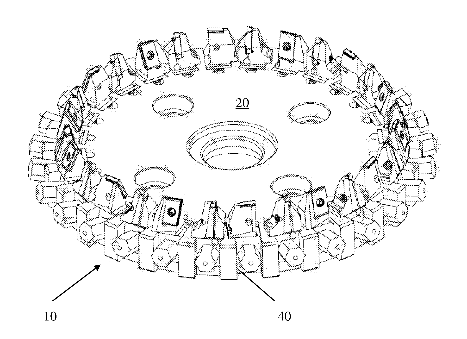
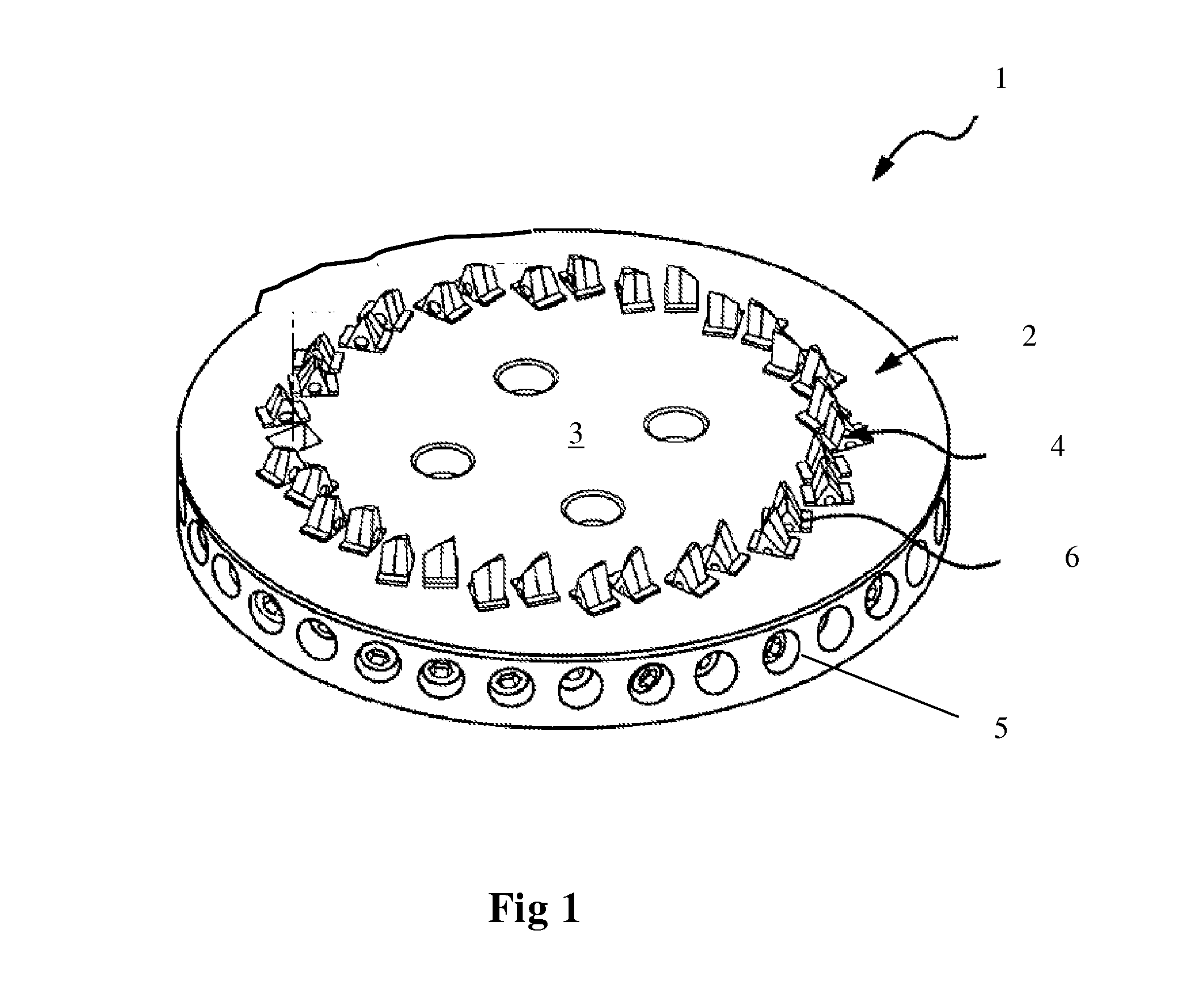
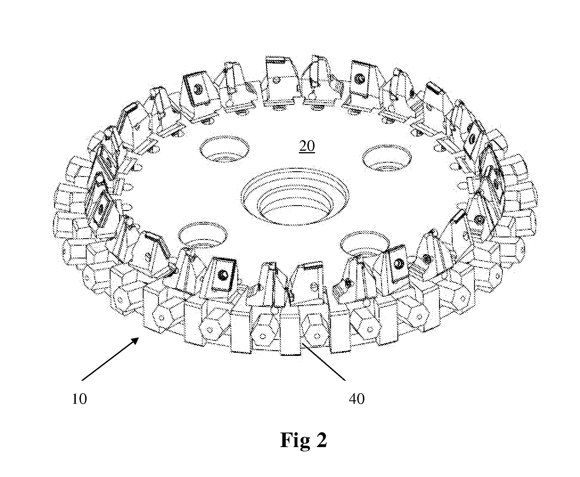
The present invention is a system for machining spiral bevel gears using a gear face hobbing cutter. The system includes different cartridges and indexable inserts that can be used to machine different parts of the gear teeth, leading to higher metal removal rate, dry cutting, longer tool life, and less set-up time. The use of different inserts for machining the flanks of the gear teeth is particularly tangential-mounted and has a rhombic basic shape, resulting in improved production efficiency and surface quality of the manufactured gear tooth. The overall design of the system and the use of specific inserts allow for better chip removal and improved tool life.

Problems solved by technology

Thus, in most of the face hobbing processes, a single plunge of the cutting tool can result in all the teeth of the gear being formed.
The blades can be re-sharpened and re-coated, which, however, consumes time and requires high cost.
However, the disadvantages generally existing in current face hobbing cutter systems are as follows: due to the employment of the high speed steel tool bits or the solid carbide blades to machine the spiral bevel gears, the productivity is comparatively low, a wet machining is required (i.e., a cooling liquid is required), the set-up time is long, and the cost and time for replacing the tool bits or regrinding the blades is high.
In the existing milling cutter system employing cartridge assemblies with indexable inserts, all the cartridges and inserts are the same, and the machining result is still not satisfactory.

Method used


Image

  • Face hobbing cutter system and indexable milling inserts for use in the same
  • Face hobbing cutter system and indexable milling inserts for use in the same
  • Face hobbing cutter system and indexable milling inserts for use in the same

Examples


example 1

[0038]A 28 cutter pocket 12″ (about 30 cm) cutter disc, on which 28 cartridge assemblies were mounted (the cartridges are obtained from Sandvik Coromant, Sweden), manufactured by Harbin No. 1 Tool Works was used. The cartridge assemblies were divided into seven sets in total, each set including 4 cartridge assemblies, two of the milling inserts of the 4 cartridge assemblies being provided as tangential-mounted inserts for machining the flanks of the spiral bevel gear teeth, and the other two of the milling inserts being provided as grooving inserts (CoroCut inserts of Sandvik Coromant, Sweden) for machining the roots of the gear teeth. The grooving inserts were provided transversely to the tangential-mounted inserts. One of the two tangential-mounted inserts was provided with its front facing the central axis, and the other thereof was provided with its front facing away the central axis, for respectively milling concave curved flanks and convex curved flanks of the gear teeth. The ...

example 2

[0041]The following parameters were employed to perform the machining: 157 RPM, 150 m / min, fzc=0.56 mm / tooth, fzf=0.112 mm / tooth, hex (flank)=0.037 mm. The machining condition was dry milling.

[0042]As a result, the cutting time for each tooth was 10 seconds. The machining speed was too slow. Besides, chip welding occurred in the milled gear, and the grooving inserts for machining the roots were chipped.

example 3

[0043]The following parameters were employed to perform the machining: 230 RPM, 220 m / min, fzc=0.08 mm / tooth, fzf=0.16 mm / tooth, hex (flank)=0.053 mm. The machining condition was dry milling.

[0044]As a result, the cutting time for each tooth was 5 seconds. The machining speed was acceptable. Besides, the quality of the milled gear is acceptable. The power load on meter is 26%.


PUM

PropertyMeasurementUnit
linear cutting velocityaaaaaaaaaa
linear cutting velocity Vcaaaaaaaaaa
height varianceaaaaaaaaaa

Abstract

A face hobbing cutter system for face hobbing spiral bevel gears. The system includes at least one set of detachable cartridge assemblies having a plurality of respective cartridge assemblies. Each cartridge assembly includes a plurality of cartridges and indexable milling inserts. A part of the inserts of each set of cartridge assemblies are rhombic, tangential-mounted inserts for milling flanks of spiral bevel gear teeth, while the other inserts are grooving inserts, which are arranged transversely to the tangential-mounted inserts, for milling roots of spiral bevel gear teeth. The tangential-mounted inserts of each set of cartridge assemblies are provided in pairs, one being provided with its front facing the central axis, and the other being provided with its front facing away the central axis, to respectively mill concave curved flanks and convex curved flanks of the spiral bevel gear teeth.

Description

TECHNICAL FIELD[0001]In the first aspect, the present invention relates to a gear face hobbing cutter system and, in particular, to an adjustable, cartridged face hobbing cutter system for face hobbing spiral bevel gears on CNC Face Hobbing machines.[0002]In the second aspect, the present invention further relates to indexable milling inserts for use in the spiral bevel gear face hobbing cutter system.BACKGROUND ART[0003]Bevel gears are widely used in trucks, construction vehicles and mining machinery. The current trend is that the potential is still in growing. At present, there are mainly two versions of bevel gears in the market. The first type is the bevel gears manufactured by Gleason, Germany (about 90% m / s), and the second type is the bevel gears manufactured by Klingelnberg, Germany (about 10% m / s). Thousands of tools for face hobbing Gleason version bevel gears exist in the market.[0004]In typical processes of face hobbing bevel gears, the milling cutter and the workpiece r...

Claims


Application Information

Patent Timeline
Patent Type & Authority Applications(United States)
IPC IPC(8): B23F21/22
CPCB23F21/226B23F17/003Y10T407/1705Y10T407/171Y10T407/1715Y10T409/105247Y02P70/10B23F21/12B23F21/16B23C5/20
Inventor JIA, TONGDUAN, YAN
Owner SANDVIK INTELLECTUAL PROPERTY AB
Learn More