Petroleum-Alternative Power Plant

a technology of alternative power plants and fossil fuels, applied in the direction of pv power plants, electric generator control, machines/engines, etc., can solve the problems of reducing the efficiency of the capture method. , to achieve the effect of optimal efficiency

Inactive Publication Date: 2014-04-17
HASSAN M HASSAN
View PDF0 Cites 8 Cited by
  • Summary
  • Abstract
  • Description
  • Claims
  • Application Information

AI Technical Summary

Benefits of technology

[0022]To increase the overall efficiency of the system, two wind turbines are used in every power tower; first wind turbine is placed at the first room with its blades are provided at the hollow center of the power tower; and the second wind turbine is provided at the second room with its blades are directly exposed to the wind stream coming from the hollow center of the building structure. The wind turbine placed at the center of the power tower is a vertical axis with Savonius, helical, multi-vanes, or Darrieus type blades. The wind turbine placed on the roof of the power tower has a horizontal axis with Savonius, helical, multi-vanes, or Darrieus type blades.
[0023]The outside surface of the building structure is divided into a number of sections. Each section forms a funnel-shaped horizontal duct to guide the winds to the blades of the first wind turbine wherein the cross-sectional area at the building structure surface is larger than the cross-sectional area at the blades of the first wind turbine. This would increase the speed of the applied wind by a factor of R, where R equals to the ratio of the cross-sectional area of the duct at the building structure surface to the cross-sectional area of the duct at the blades of the first turbine. Every funnel-shaped horizontal duct is provided with a valve and a control subsystem to prevent winds flowing in the opposite direction from the hollow center to the outside surface of the building structure and to control and direct all winds to the blades of the first wind turbine for optimal efficiency. All wind streams from all compass directions are applied to the blades of the first wind turbine where wind energy is converted to electricity.
[0024]There is a barrier preventing wind streams from flowing downward in the hollow center from the first wind turbine to the first room of the building structure; therefore the wind stream flows upward in the hollow center towards the blades of the second wind turbine. The hollow center forms a funnel-shaped vertical duct from a point above the blades of the first wind turbine to a point at or just below the blades of the second wind turbine to accelerate the wind stream further. The funnel-shaped vertical duct is provided with a valve and a control subsystem to prevent winds flowing downward in the hollow center of the building structure and to control and direct wind flow to the blades of the second wind turbine for optimal efficiency. The wind stream in the funnel-shaped vertical duct is applied to the blades of the second wind turbine where wind energy is converted to electricity. The management control subsystem combines electricity from the first wind turbine and said second wind turbine, and selectively delivering electricity to a power grid and an electric load. The electric load is a house, a subdivision, a commercial unit, an industrial plant, or any other entity that requires electricity.

Problems solved by technology

The desire to capture the wind, solar, and thermal energies to provide power is not new; however, the methods and apparatus to perform the capture have evolved only slowly and often inefficiently over a long period of time.
First, they require two or three very long blades that must be placed very high into the air so as to be positioned in a relatively smoothly flowing air current and they must also be mounted high enough so that the whirling blades do not strike the ground, trees, buildings, wires, and the like.
Second, when it comes to wildlife windmills provide danger to birds and animals alike. Birds can fly into one blade and animals can climb to the windmill equipment. Therefore, windmills may cause danger to wildlife, impact on the environment, and may demand high cost of maintenance continuously.
Third, due to the great length of the blades and height of the mounting structures, the mounting towers can be enormous and require stabilizing wires anchored hundreds of feet from the mounting tower, hence, occupying a huge amount of real estate.
Fourth, the spinning blades can create unpleasant and disruptive noise and vibration which somewhat can be unbearable for residential or even commercial neighborhoods.
Fifth, the aesthetic qualities of the technology are poor since the windmills are quite big, and they do create somewhat of a blot on the landscape.
Sixth, current windmills are exposed to the destructive power of nature, such as storms, hurricanes, tornadoes, that can easily damage the windmill's components and may cause significant loss to life and property.
Nevertheless, since wind flow within urban and suburban environments is turbulent and veering.
Increased turbulence levels yield greater fluctuations in wind speed and direction continuously, hence, reducing the efficiency of the turbine due to opposing winds or the frequent change in wind directions.
Having disturbed wind or veering wind directions will reduce the turbine efficiency significantly.
This may occur due to the fact that the minimum threshold of wind speed required for the turbine to operate is not met.
In other words, simply many turbines will not generate power at low wind speed conditions.
Tenth, when windmills are exposed to sun and rain, snow and sleet, storms and other elements, they are more likely to rust and break up gradually.
Therefore, they often require high maintenance or frequent replacements to very expensive windmill equipment and parts.
Wrongly thinking that this approach will solve the problems of noise, vibration, and other problems cited above.
Placing windmills on the tops of houses and occupied buildings is not only impractical, inefficient, and noisy; it may be also dangerous to life and property due to the heavy weight of the windmill equipment that often a house structure cannot support.
Nevertheless, the amount of the generated electricity is insignificant in comparison to the cost of windmill equipment and the structural changes in a dwelling or an occupied building.
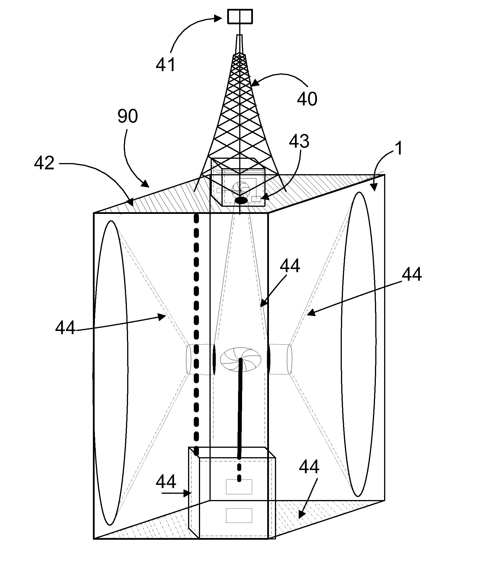
Although, these prior art's systems and methods fulfill their respective, particular objectives and requirements, they do not disclose the structure of the invention of the applicant for a new reliable, high-efficiency power plant that harnesses wind streams from any compass direction where all wind streams work jointly and cooperatively despite veering and turbulent environments; in addition to harnessing solar and thermal energies to generate the maximum power and to produce non-fossil fuel, if required.
Presently, no known high-power, high-efficiency, environmentally and wildlife friendly, safe and low maintenance, petroleum-alternative power plant and non-fossil fuel production system exist that provide usable electrical output and non-fossil fuel with ordinary and variable wind flow arriving from any compass direction, and with harnessing solar and thermal energies, while being visually pleasing, substantially inaudible and vibration free, as well as protected from the elements.

Method used


Image

  • Petroleum-Alternative Power Plant
  • Petroleum-Alternative Power Plant
  • Petroleum-Alternative Power Plant

Examples


Embodiment Construction

[0053]The detailed description set forth below is intended as description of the presently preferred embodiments of the invention, and is not intended to represent the only form in which the present invention may be constructed or utilized. The description sets forth the functions and sequences of steps for constructing and operating the invention. It is to be understood, however, that the same or equivalent functions and sequences may be accomplished by different embodiments and that they are intended to be encompassed within the scope of the invention.

[0054]With reference now to the drawings in given FIGS. 1-23, the preferred embodiments will now be described in detail. A petroleum-alternative power plant and non-fossil fuel production system in accordance with the present invention is designated generally as “100”. The power plant 100 consists of a plurality of power towers. FIGS. 1-15 illustrate several power towers using several building structures, namely: a rectangular buildi...


PUM


Abstract

The present disclosure includes a petroleum-alternative power plant system harvesting wind, solar, and thermal energies. The system may include at least one two-wind-turbine power tower building where the outside surface of the building is divided into a number of sections. Each section forms a funnel- shaped duct to guide and accelerate the wind streams toward the vanes of the first wind turbine; then wind streams accelerated further and guided toward the vanes of a second wind turbine. The system may also include solar receptors, solar tower, and thermal receptors to harvest more energy. A management control subsystem is provided to combine electricity, and selectively delivering electricity to any electric load, a non-fossil fuel production subsystem, and the power grid.

Description

CROSS REFERENCE TO RELATED APPLICATION[0001]Not ApplicableSTATEMENT REGARDING FEDERALLY SPONSORED RESEARCH OR DEVELOPMENT[0002]Not ApplicableFIELD OF THE INVENTION[0003]The present invention relates generally to power plants and more specifically to petroleum-alternative power plants and non-fossil fuel production system harvesting wind, solar, and thermal energies.BACKGROUND OF THE INVENTION[0004]Growing global energy demands put pressure on both the supply and the prices of oil, gas, and coal. As fossil energy sources today are an important part of maintaining a stable energy network in the world, it is crucial to use these resources in a sustainable and high efficiency manner. Even with the increased efficiency in both production and use of fossil fuel, the gradual depletion and the ultimate exhaustion of fossil fuel is an undisputable reality. Therefore, innovations in all areas of sustainable energy supply and energy consumption are among the most effective tools we have to fig...

Claims


Application Information

Patent Timeline
Patent Type & Authority Applications(United States)
IPC IPC(8): F03D9/00
CPCF03D9/003F03D1/04F05B2240/9112F03D9/255H02S10/12Y02B10/10Y02B10/30Y02B10/70Y02E10/50Y02E10/72Y02E10/728
Inventor HASSAN, M. HASSAN
Owner HASSAN M HASSAN
Why Eureka
Try Eureka