Extruded table for a brake shoe

a technology of brake shoe and extrusion table, which is applied in the direction of friction lining, fluid actuated drum brake, manufacturing tools, etc., can solve the problems of difficult removal and replacement of brake lining when they become, affecting the service life of the brake shoe, and requiring the replacement of the brake lining. , to achieve the effect of reducing the operating temperature facilitating the replacement of the brake lining, and improving the retention

Inactive Publication Date: 2014-05-01
BENDIKS SPAJSER FAUNDEJSHN BREJK LLK
View PDF11 Cites 11 Cited by
  • Summary
  • Abstract
  • Description
  • Claims
  • Application Information

AI Technical Summary

Benefits of technology

[0007]The present invention relates to a brake shoe for a drum brake. In particular, the present invention relates a brake shoe that may be formed by extrusion and that includes features for reducing operating temperatures of the brake linings and / or for improved retention and easier replacement of the brake linings.
[0009]A brake shoe for a drum brake in accordance with another embodiment of the present invention includes a brake table defining a radially inner side and a radially outer side. The brake shoe further includes first and second webs disposed on the radially inner side of the brake table and configured to support the brake table. The brake shoe further includes first and second brake linings disposed on the radially outer side of the brake table. The brake table is a unitary body and is configured at first and second ends and a point intermediate the first and second ends to engage the first and second brake linings and prevent circumferential movement of the first and second brake linings relative to the brake table.
[0012]A brake shoe in accordance with the present invention represents an improvement relative to conventional brake shoes. By forming the brake table in such a way that it is configured to prevent circumferential movement of the brake linings relative to the brake table as in one or more of the above-described embodiments, the brake linings may be attached to the brake table with fewer fasteners. As a result, easier removal and replacement of worn linings is facilitated. Further, the linings may be attached in a manner to reduce stress in tension and shear during a brake application. By forming the brake table with fins and / or materials having high specific heats and thermal conductivity as in one or more of the above-described embodiments, the operating temperatures on the linings may be reduced thereby reducing wear and frequency of replacement. Further, the use of different, corrosion resistant materials for the brake table enables a reduction in rust buildup between the table and linings thereby increasing the life of the brake linings and reducing brake drag and excessive noise.

Problems solved by technology

First, in a conventional brake shoe, the brake linings are coupled to the brake table with a relatively large number of rivets which makes it difficult to remove and replace the brake linings when they become worn.
Further, portions of the linings between the rivets are subjected to relatively high stress in compression, tension, and shear during braking, but some types of linings do not resist stress in tension and shear as well as they do in compression.
Second, replacement of the brake linings is required—despite the difficulties noted above—in part due to relatively high operating temperatures that can substantially reduce the life of the brake linings in conventional brake shoes.
Rust buildup between the table and linings, however, can result in cracked or broken linings, dragging brakes or excessive noise.

Method used


Image

  • Extruded table for a brake shoe
  • Extruded table for a brake shoe
  • Extruded table for a brake shoe

Examples


Embodiment Construction

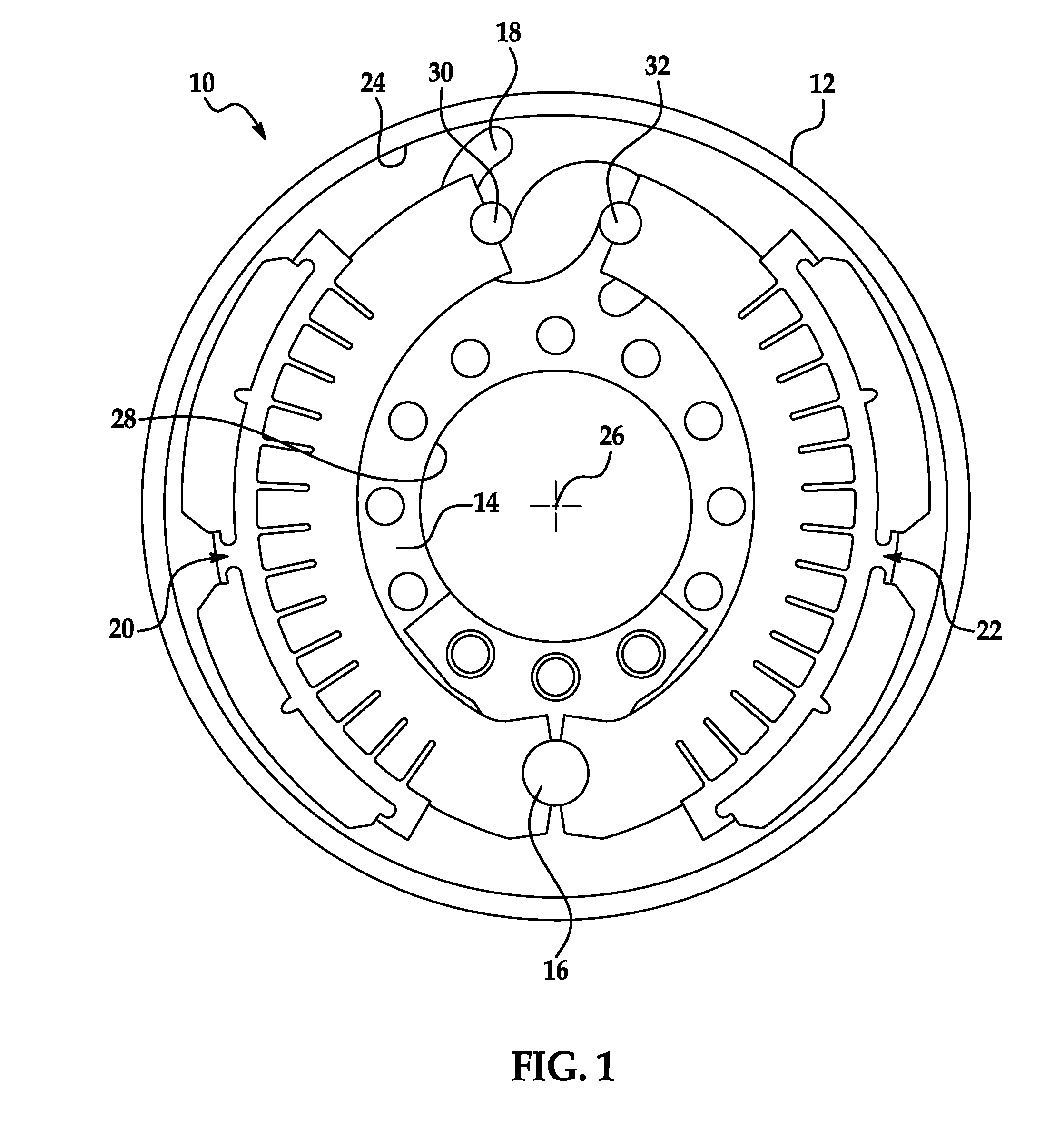
[0021]Referring now to the drawings wherein like reference numerals are used to identify identical components in the various views, FIG. 1 illustrates a drum brake 10. Brake 10 is particularly adapted for use in heavy trucks. It should be understood, however, that brake 10 may be used on a wide variety of vehicles and in non-vehicular applications. Brake 10 may include a brake drum 12, a brake spider 14, an anchor 16, an actuating member 18, and brake shoes 20, 22 in accordance with the present invention.

[0022]Brake drum 12 provides a braking surface 24 and is conventional in the art. Drum 12 may be made from conventional metals and metal alloys such as steel or cast iron. Drum 12 is annular and rotates with the vehicle wheel or wheels at one end of an axle about a central axis 26 extending through the axle (and into and out of drawing in FIG. 1).

[0023]Brake spider 14 is provided to mount the various components of brake 10. Spider 14 defines a central aperture 28 through which the v...


PUM

PropertyMeasurementUnit
lengthaaaaaaaaaa
widthaaaaaaaaaa
circumferential movementaaaaaaaaaa

Abstract

A brake shoe for a drum brake includes an arcuate brake table defining radially inner and outer sides. First and second webs are disposed on the radially inner side of the brake table and configured to support the brake table. One or more brake linings are disposed on the radially outer side of the brake table. In one embodiment, the brake table defines a plurality of fins projecting radially inwardly from the radially inner side of the brake table, each of the plurality of fins having a length in a radial direction. In another embodiment, the brake table is a unitary body and is configured at first and second ends and a point intermediate the first and second ends to engage first and second brake linings and prevent circumferential movement of the first and second brake linings relative to the brake table. The brake table may comprise extruded aluminum.

Description

BACKGROUND OF THE INVENTION[0001]a. Field of the Invention[0002]This invention relates to drum brakes. In particular, the invention relates to a brake shoe for a drum brake in which a brake table of the shoe is formed through extrusion and includes features for reducing operating temperatures of the brake linings and for improved retention and easier replacement of the brake linings.[0003]b. Background Art[0004]A conventional drum brake includes a brake drum that rotates with a wheel or wheels proximate to one end of an axle. The drum defines a radially inner braking surface. A brake spider is disposed about the axle and a pair of brake shoes are pivotally mounted at one end to the brake spider. The opposite end of each brake shoe is engaged by an actuator such as a cam or hydraulic piston or wedge to move the brake shoes between positions of engagement and disengagement with the braking surface of the brake drum.[0005]The brake shoes include one or more arcuate webs that are couple...

Claims


Application Information

Patent Timeline
Patent Type & Authority Applications(United States)
IPC IPC(8): F16D65/08F16D65/09B23P11/00F16D65/827
CPCF16D51/22F16D51/24F16D65/08F16D65/827F16D69/0416F16D2069/0433F16D2069/0441F16D2069/0491F16D2125/30F16D2125/66Y10T29/49826
Inventor BERWANGER, FRED W.
Owner BENDIKS SPAJSER FAUNDEJSHN BREJK LLK
Why Eureka
Try Eureka