
Encoder element and method for the manufacture thereof

a technology of encoder elements and manufacturing methods, applied in the direction of instruments, nuclear engineering, transportation and packaging, etc., can solve the problems of high rejection rate during production, high cost, and complex known methods, and achieve the effect of high production efficiency, high production efficiency, and easy and controlled automation

Inactive Publication Date: 2014-05-01
ROBERT BOSCH GMBH
View PDF11 Cites 4 Cited by
  • Summary
  • Abstract
  • Description
  • Claims
  • Application Information

AI Technical Summary

Benefits of technology

The present invention provides a method for manufacturing an encoder element that is fast, cost-effective, and secure. The method involves applying a magnetic layer to a base body using a spraying process, resulting in a tight joint that eliminates the risk of water or other liquids entering between the base body and the magnetic layer. No post-processing steps are necessary, and the method allows for easy and controlled automation. The use of rubber or synthetic rubber is dispensed with, resulting in improved concentricity properties and reduced imbalances. The minimum layer width and thickness of the magnetic layer can be determined, and the method is flexible and cost-effective for different production needs. Nanostructures are generated on the surface of the base body to improve adhesiveness of the spray granules, and a cold gas spraying method with nitrogen or helium gas can be used for homogeneous distribution of magnetic particles. The use of pure magnetic powder or magnetic powder sheathed with plastic material results in an anti-corrosion layer, and an additional anti-corrosion layer may be applied after the magnetic layer. This improves the service life of the encoder element.

Problems solved by technology

However, drawbacks of the rubber magnet element applied by vulcanization are that this results in relatively high costs and additionally may only be applied in a certain minimum thickness due to the vulcanization process.
However, this known method is also very complex and must be carried out with maximum manufacturing precision, which in practice results in high reject rates during production.
This results in major cost and time advantages.
In addition, a particularly tight joint may be achieved between the magnetic layer and the base body, so that in particular salt water or the like is not able to penetrate between the magnetic layer and the base body.

Method used


Image

  • Encoder element and method for the manufacture thereof
  • Encoder element and method for the manufacture thereof
  • Encoder element and method for the manufacture thereof

Examples


Embodiment Construction

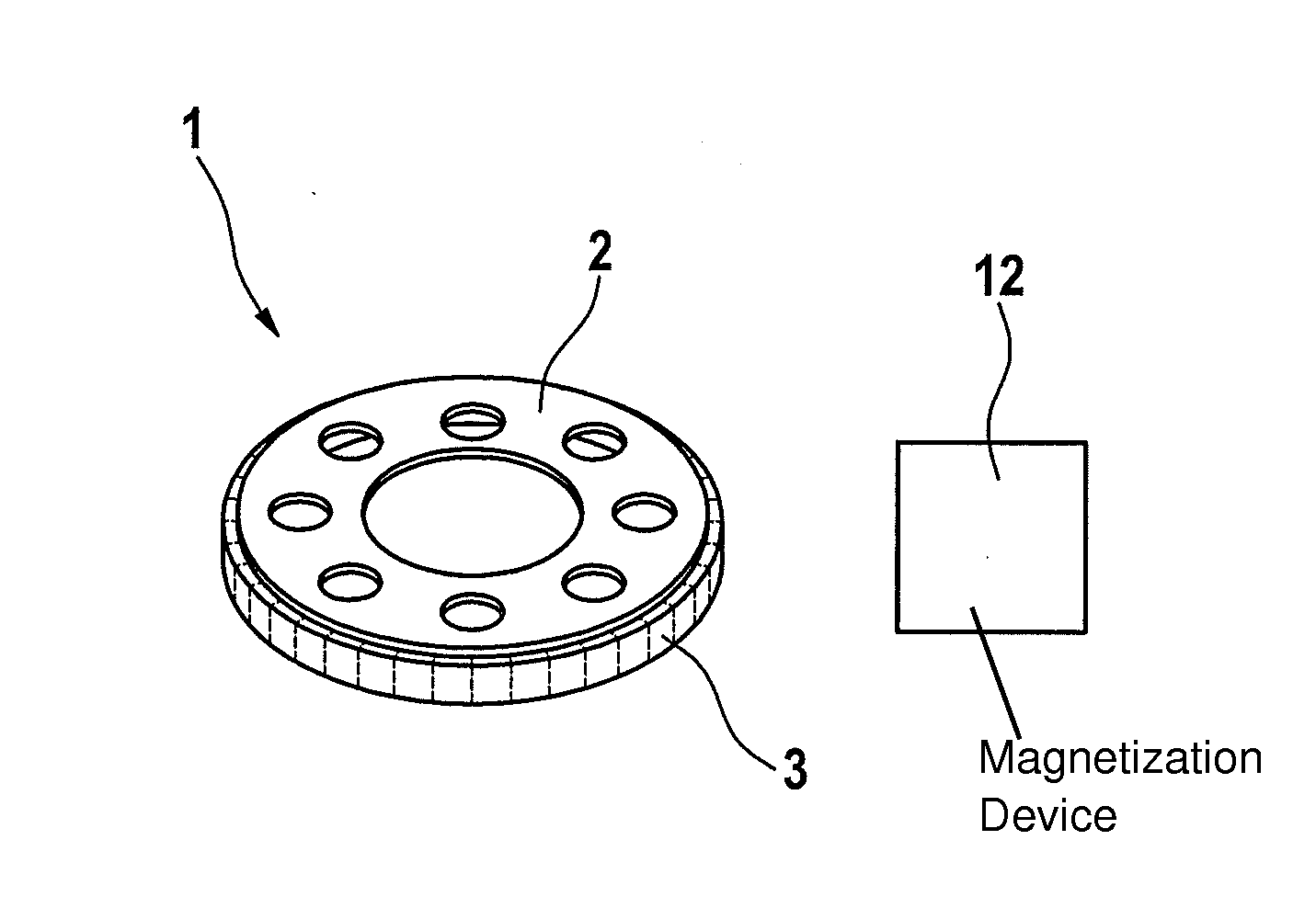
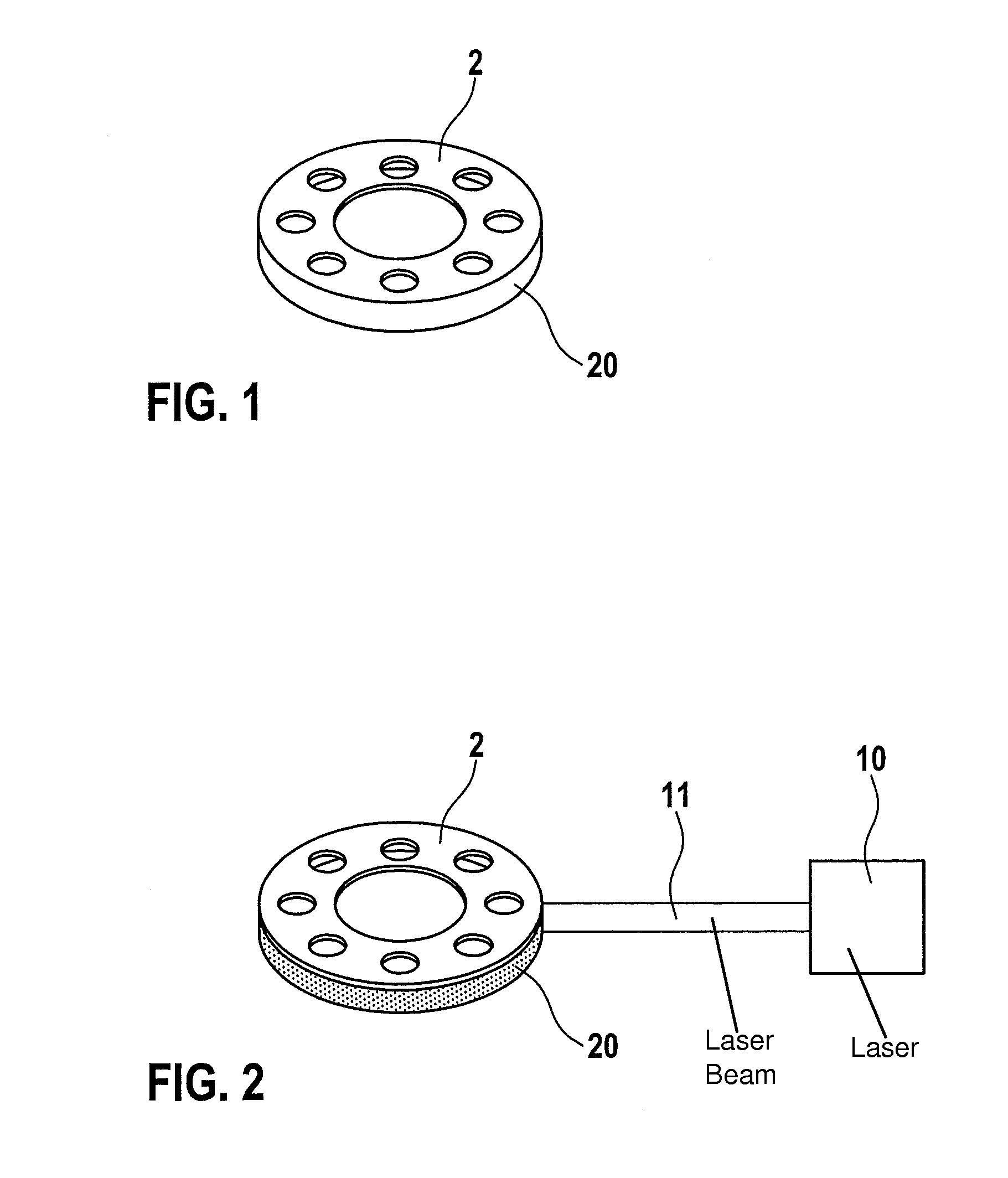
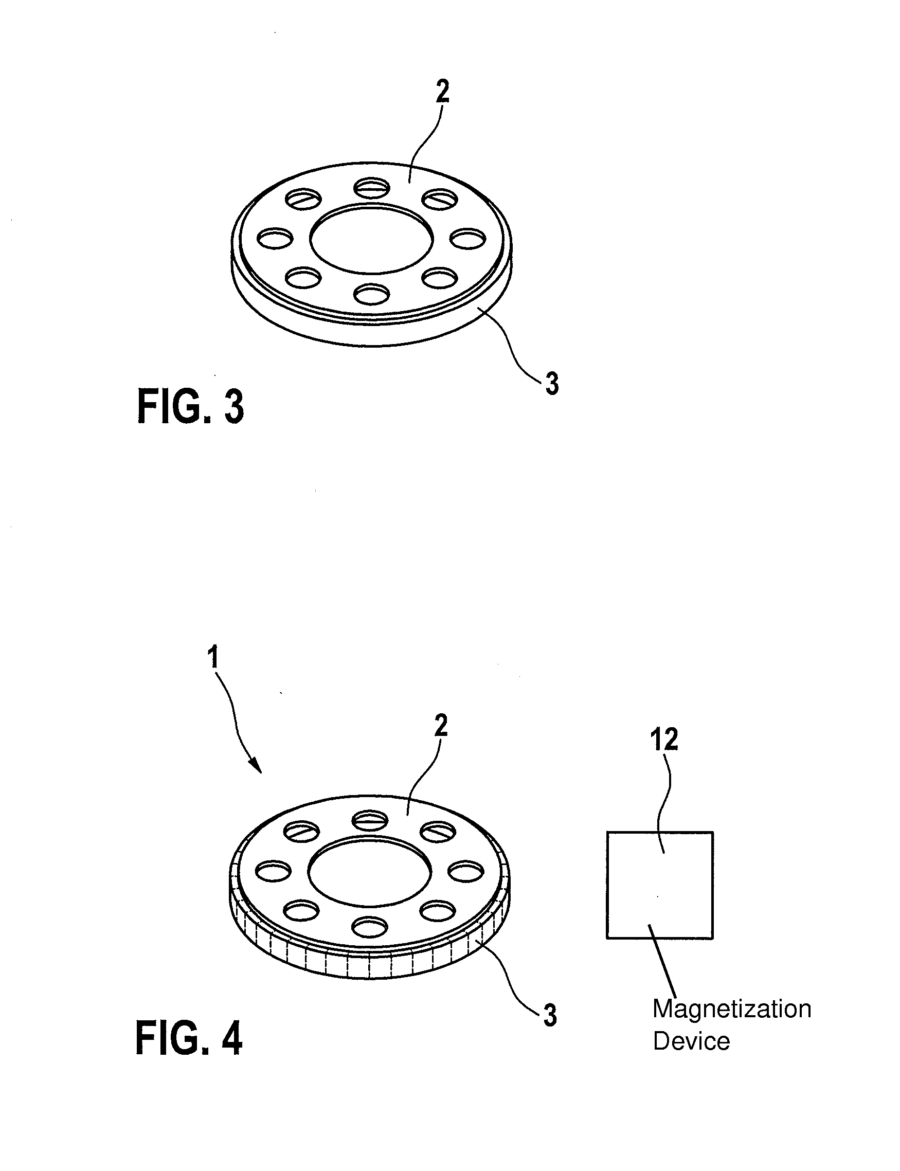
[0017]A method according to the present invention for manufacturing an encoder element and an encoder element 1 according to the present invention will be described hereafter in detail with reference to FIGS. 1 through 4.

[0018]Encoder element 1 according to the present invention is an encoder wheel in this exemplary embodiment, which includes a circular base body 2 and a magnetic layer 3. Magnetic layer 3 is situated for this purpose on an outer circumferential surface 20 of base body 2 with the aid of a direct, integral joint. Magnetic layer 3 is applied to outer circumferential surface 20 of base body 2 with the aid of a spraying process, in particular cold gas spraying or cold plasma spraying. Magnetic layer 3 may be manufactured from pure magnetic powder, or a magnetic powder in which the individual magnetic particles are situated in a plastic sheathing. Along the circumference, magnetic layer 3 has alternating polarizations to provide a multipole encoder wheel.

[0019]The method ...


PUM


Abstract

A method is described for manufacturing an encoder element having a base body and a magnetic layer situated on the outer circumference of the base body, including the following steps: providing the base body; providing a magnetic or magnetizable powdery material; directly applying the powdery material to the outer circumference or to an end face of the base body to generate the magnetic layer in such a way that an integral, direct joint is created between the base body and the magnetic layer; and magnetizing the applied magnetic layer.

Description

FIELD OF THE INVENTION[0001]The present invention relates to a method for manufacturing an encoder element and to such an encoder element having magnetic properties.BACKGROUND INFORMATION[0002]Magnetic encoder wheels are used, for example, in the field of the automotive industry in a variety of ways as part of ABS systems, on camshafts, on crankshafts and on steering systems. To manufacture such encoder wheels, a rubber material mixed with magnetic filler material is usually vulcanized onto a metal wheel. Such encoder wheels have been successfully employed in particular in the field of automotive engineering, where high alternating stresses due to changing temperatures and, in the winter for example, contact with salty water and the like are possible. However, drawbacks of the rubber magnet element applied by vulcanization are that this results in relatively high costs and additionally may only be applied in a certain minimum thickness due to the vulcanization process. Moreover, an ...

Claims


Application Information

Patent Timeline
IPC IPC(8): G01D5/12
CPCG01D5/12G01D5/244
Inventor HUND, PAULBOMMER, LARSSCHNEIDERHAUTMANN, NIKOLAUSDIEKMANN, RALFWOLFANGEL, NADJA
Owner ROBERT BOSCH GMBH
Learn More