Electric power steering control device and electric power steering control method

a control device and electric power steering technology, applied in the direction of electrical steering, electric motor control, transportation and packaging, etc., can solve the problems of excessive limit of motor current, and early limitation of motor current, and achieve the effect of increasing assist torqu

Active Publication Date: 2014-05-01
MITSUBISHI ELECTRIC CORP
View PDF1 Cites 10 Cited by
  • Summary
  • Abstract
  • Description
  • Claims
  • Application Information

AI Technical Summary

Benefits of technology

[0011]According to the present invention, the current upper-limit value for protection against heating for each component is sequentially corrected in consideration of two thermal characteristics, which are a self-heating characteristic and an ambient-temperature characteristic, for each component used in the control device. The smallest current upper-limit value is selected from the results of correction to perform the current control. As a result, it is possible to obtain the electric power steering control device and the electric power steering control method, which can realize a more appropriate countermeasure against heat in accordance with the thermal characteristic of the component used to supply the motor current, and can generate a larger assist torque than a conventional one.

Problems solved by technology

However, the conventional technologies have the following problems.
However, the conventional devices put so high priority on safety that there is a tendency to limit the motor current excessively.
Therefore, when a high current flows as the motor current, the motor current is limited early.
Then, even after the motor current is reduced or the driving is stopped, the limitation of the motor current is continued for a relatively long period of time, which leads to reduced assist of the steering force.

Method used


Image

  • Electric power steering control device and electric power steering control method
  • Electric power steering control device and electric power steering control method
  • Electric power steering control device and electric power steering control method

Examples


first embodiment

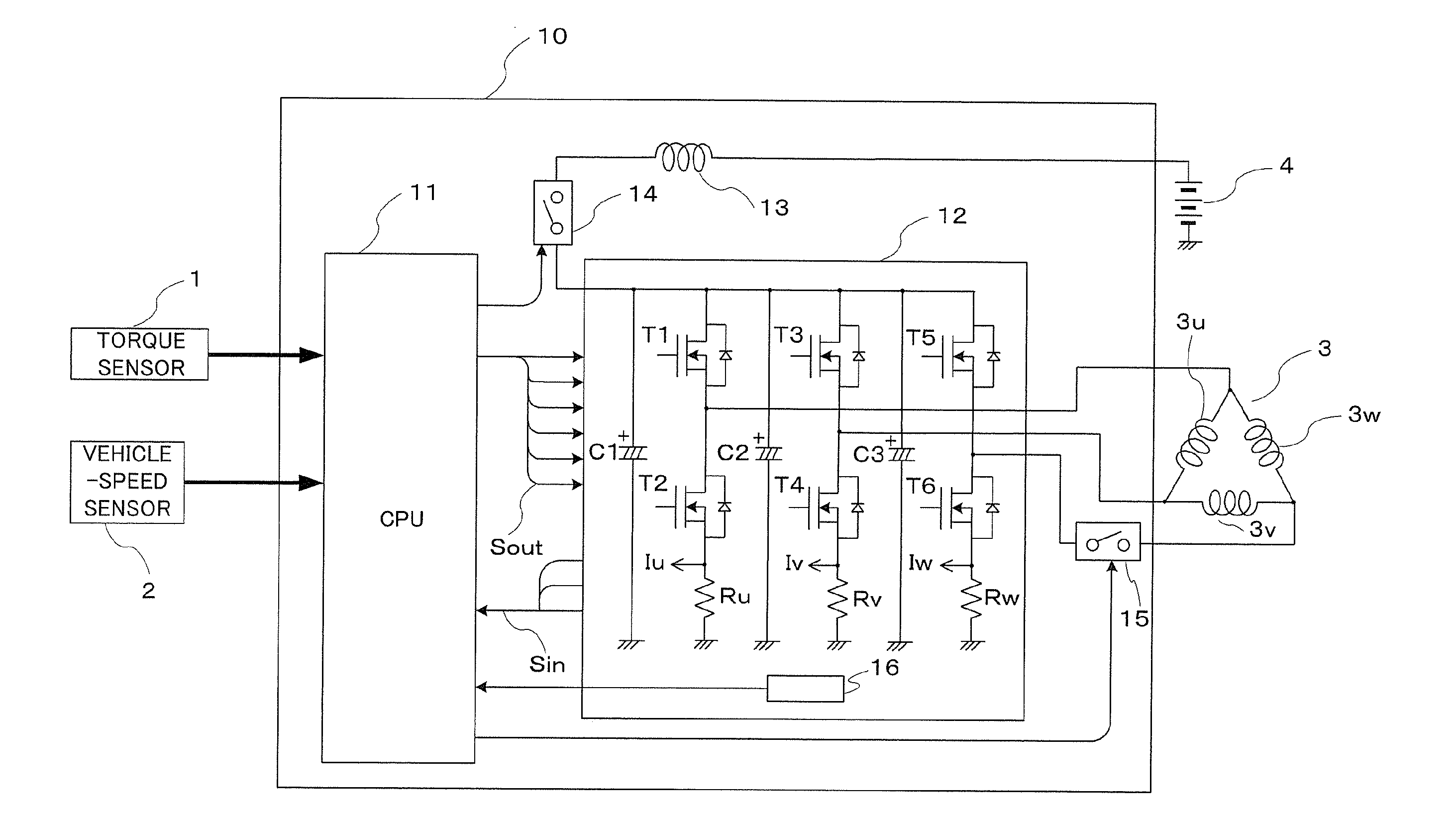
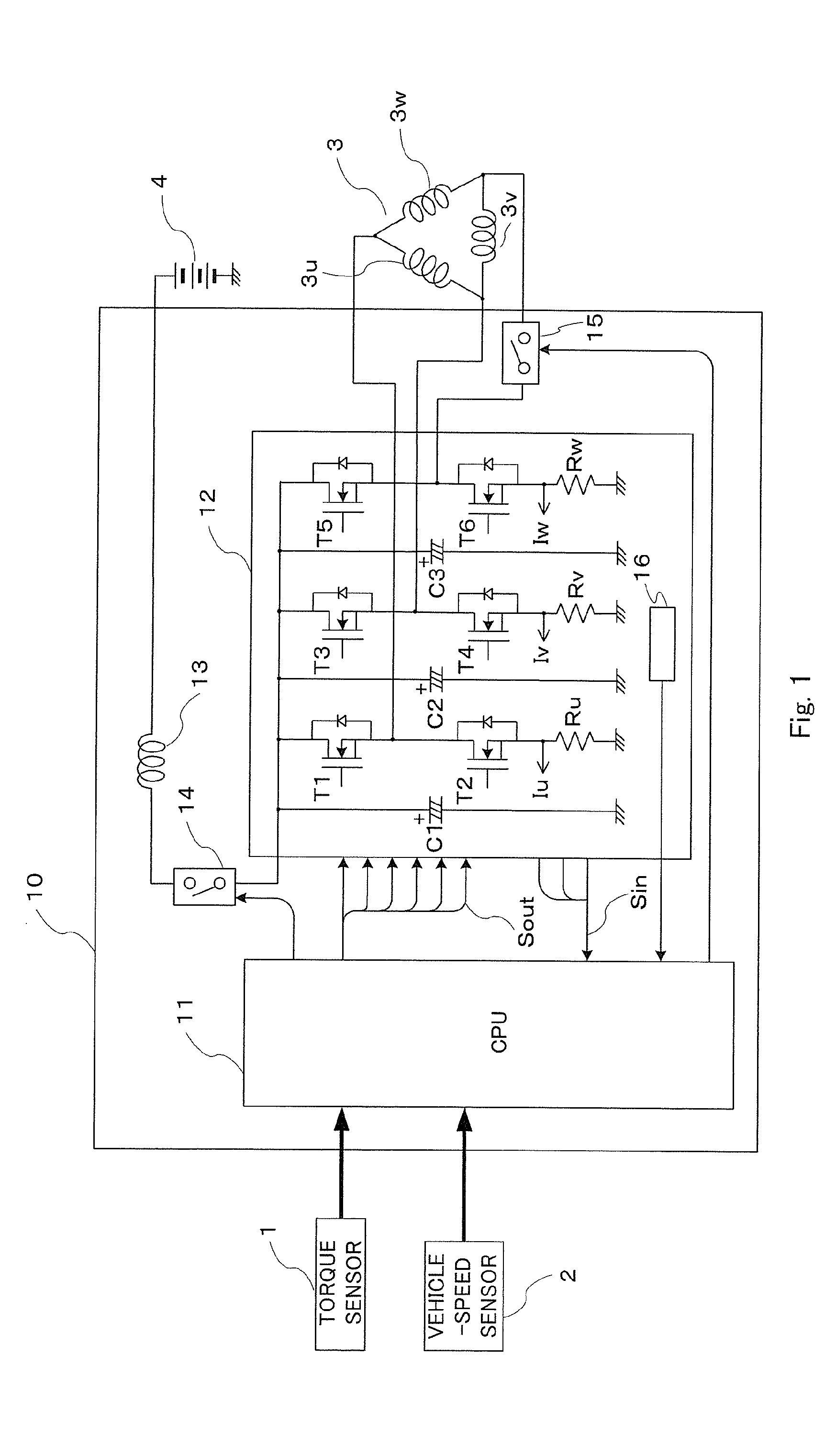
[0021]FIG. 1 is an overall configuration diagram illustrating an electric power steering control device according to a first embodiment of the present invention. The electric power steering control device of the first embodiment includes a torque sensor 1, a vehicle-speed sensor 2, a motor 3, a battery 4, and a control unit 10. A three-phase brushless motor is used as the motor 3. A state in which the motor 3 includes coils 3u, 3v, and 3w is herein exemplified.

[0022]The control unit 10 includes a CPU 11, a driving section 12, a choke coil 13, a power-supply relay 14, and a motor relay 15. Further, the driving section 12 includes six switching elements T1 to T6 as represented by FETs, three noise-prevention capacitors C1, C2, and C3, and three shunt resistors Ru, Rv, and Rw for detecting a current flowing through the motor 3.

[0023]The torque sensor 1 is provided in the vicinity of a steering wheel (not shown) of a vehicle, and detects a steering torque applied by a driver. The vehicl...

second embodiment

[0085]The first embodiment has described the case where the overheat-protection characteristic (coefficient) of the component having a large amount of self-heating is calculated in consideration of both the characteristic depending on the self-heating and the characteristic depending on the ambient temperature. On the other hand, a second embodiment of the present invention describes the case where the two characteristics are treated as a single characteristic.

[0086]Referring to FIG. 4 referred to above, the following is understood. In the low-current regions (A1 to C1 and A2 to C2), the two characteristics do not have a large difference. In the high-current regions (C1 or larger and C2 or larger), the two characteristics apparently have a difference.

[0087]FIG. 5 is a graph showing an overheat-protection characteristic according to the second embodiment of the present invention. As shown in FIG. 5, when the current is smaller than the high-current region, set values (A3, B3, and C3)...

third embodiment

[0092]A third embodiment of the present invention describes the case where a single component has a plurality of characteristics in accordance with an atmospheric temperature. In the control unit 10 illustrated in FIG. 1 referred to above, the temperature sensor 16 is mounted in the vicinity of the heat-generating components (switching elements T1 to T6, for example) of the driving section 12 or the heat sink for radiating the heat of the heat-generating components.

[0093]The temperature sensor 16 may be a thermosensitive element such as a thermistor. The CPU 11 reads temperature information detected by the temperature sensor 16 to obtain a temperature in the vicinity of the location where the temperature sensor 16 is mounted.

[0094]FIG. 6 is an overheat-protection characteristic diagram according to the third embodiment of the present invention. In the characteristic diagram of FIG. 6, a characteristic 23 indicated by a solid line corresponds to a basic characteristic 23 of the corre...


PUM


Abstract

Provided is an electric power steering control device which can realize a more appropriate countermeasure against heat in accordance with a thermal characteristic of a component used to supply a motor current. The electric power steering control device for assisting a steering force of a steering wheel of a vehicle including a control unit (10). The control unit (10) prestores a first overheat-protection characteristic corresponding to self-heating and a second overheat-protection characteristic corresponding to an ambient temperature for each component (12 to 15) mounted in the control unit as an overheat-protection characteristic specifying a correspondence relationship between a heat-source current value of the each component and an overheat-protection coefficient, and sequentially corrects a current upper-limit value obtained for the each component by using overheat-protection coefficients of both characteristics to continue current control in accordance with a smallest current upper-limit value of results of the correction.

Description

BACKGROUND OF THE INVENTION[0001]1. Field of the Invention[0002]The present invention relates to an electric power steering control device and an electric power steering control method, which uses an electric motor to assist a steering force of a steering wheel, in particular, to a countermeasure against heat for the control device.[0003]2. Description of the Related Art[0004]When a motor is driven in a conventional electric power steering control device, a necessary current is controlled to flow to generate a necessary assist torque. Therefore, a countermeasure against heat generation is required for each of sections. Among the sections, a controller includes a large number of components to supply the current to the motor. Therefore, in the controller, a countermeasure against heat has been taken not only by improving heat radiation performance of each of the components but also by limiting the current to variably change a control amount.[0005]As a conventional device, there exists...

Claims


Application Information

Patent Timeline
Patent Type & Authority Applications(United States)
IPC IPC(8): H02H7/08B62D5/04B62D6/00H02P6/06H02P6/08H02P6/12H02P6/28
CPCH02H7/08B62D5/046B62D5/0496H02P29/68
Inventor IWAMI, EIJIGOTO, TAKASHIZENIYA, SUSUMUTANAKA, DAISUKE
Owner MITSUBISHI ELECTRIC CORP
Why Eureka
Try Eureka