Exterior Wall Assembly Systems

a technology of external walls and assemblies, applied in the direction of couplings, manufacturing tools, mechanical devices, etc., can solve the problems of reducing the water resistance of the barrier, so as to increase the water resistance of the system, prevent water, and improve the water resistance. the effect of the water resistan

Inactive Publication Date: 2014-05-01
BRADY TODD A
View PDF2 Cites 6 Cited by
  • Summary
  • Abstract
  • Description
  • Claims
  • Application Information

AI Technical Summary

Benefits of technology

[0011]In still another embodiment, the attachment strip includes a space located on the rear side of the attachment strip wherein foam core insulation is inserted. This provides extra water resistive characteristics when the lath is secured to the attachment strip after a mounting device secures the lath to the attachment strip. The same mounting device penetrates the foam core insulation layer before penetrating the sheathing. By locating the insulation layer adjacent to the penetration hole, the insulation layer blocks the entrance of water. Increased water resistive features also include using attachment strips with multiple sections and a long vertical leg that separates the multiply connected attachment strips. By having multiply connected attachment strips, one attachment strip can be secured to the sheathing, then a large piece of insulation can be placed on top of the attachment strip connected directly to the sheathing while the second connected attachment strip can be secured to the thick insulation without penetrating the sheathing. This is advantageous because it creates several layers of protection between the lath itself, and the sheathing with the penetration holes created by the mounting device.
[0012]There is provided a system for securing lath to a wall, the system comprising one or more framing members, a sheathing secured to the framing members, a water resistive barrier adjacent to the sheathing, a lath, an attachment strip for securing, an insulation layer between the attachment strip and the moisture resistive barrier, a mounting device that secures the lath, the attachment strip, the framing and sheathing together. The system also has outer layers of plaster coats, which can be a scratch coat, a brown coat, and a finishing coat. To further increase water resistive properties of the system, the attachment strip can have multiple portions having different heights. This allows for an increased space between the lath and the sheathing, where an insulation layer can be placed, and which further prevents water from seeping in from the out layers of the system into the sheathing. This extra space also creates an air barrier / water drainage region, which allows for water to migrate down a wall, instead of into the sheathing.
[0013]In another embodiment, there are provided two water resistive barriers, a first water resistive barrier attached to the sheathing, and a second water resistive barrier adjacent to the lath. Between the first and second water resistive barriers is the air barrier / water drainage region, the air barrier created by the depth of the attachment strip. Any moisture that enters from the outside wall through the lath and into the second water resistive barrier would be prevented from seeping back to the outer wall, and also be prevented from seeping further into the inner walls by the first water resistive barrier on the sheathing. The air barrier / water drainage region provides a vertical escape route for any moisture that enters the air barrier / water drainage space.
[0014]In still a further embodiment, there is provided gaps or spaces between sheets of water resistive barriers adjacent to the lath. These water resistive barriers run vertical on a lath when placed on a wall, and the vertical spaces between each sheet of the water resistive barrier allow wet stucco to seep through the spaces in the lath and contact the inner wall or sheathing directly, without being blocked by the water resistive barrier. When the plaster reaches the inner wall through the spaces between the sheets of the water resistive barriers, they create additional support in the form a vertical plaster rib or a vertical line of smaller openings (e.g. holes) that helps prevent bowing of the plaster wall between the attachment strips. To further aid in keying, the water resistive barrier does not cover the attachment strip so that when the wet plaster is applied, the attachment strips are encased with plaster.
[0015]In still a further embodiment an attachment strip with an open space to allow the wet plaster to integrate and key with the strip has return legs that, 1) have minimal contact with the water resistive barrier / sheathing which further reduces thermal transfer, 2) the return legs are radiused metal that create a soft touch feature as not to dig-in or tear the water resistive barrier, and 3) are designed to create a gasket like seal, vertically on both sides of the screw feature to protect the screw penetration from water intrusion. Furthermore, the return legs control horizontal water migration by keeping water controlled within the vertical stud bay, and allowing it to escape only vertically to the bottom of the wall.

Problems solved by technology

These traditional methods of attaching the metal lath to the sheathing creates multiple penetrations of the moisture resistive barrier and can cause tearing of the barrier that compromises its water resistant purpose.
However, there are still problems with current furring strips.
Moreover, the attachment of the lath to the furring strip is labor intensive and difficult.
This can be very tedious and time consuming since several attachment points using wire ties, staples, screws or nails are needed to properly secure the lath to the furring strip so that it does not fall off the wall due the weight of the lath, after plaster is applied to it.
Traditional metal furring strips have also been an unwanted source of thermal transfer from interior to exterior walls and vice versa.
Conventional furring strips are also not designed to accommodate the latest insulation technologies or accommodate improved drainage planes within wall systems.

Method used


Image

  • Exterior Wall Assembly Systems
  • Exterior Wall Assembly Systems
  • Exterior Wall Assembly Systems

Examples


Embodiment Construction

[0119]The following description is of the best-contemplated mode of carrying out the invention. This description is made for the purpose of illustrating the general principles of the invention and should not be taken in a limiting sense. The scope of the invention is best determined by reference to the appended claims. Preferable embodiments of the present invention are described with reference to the FIGS. 1-30.

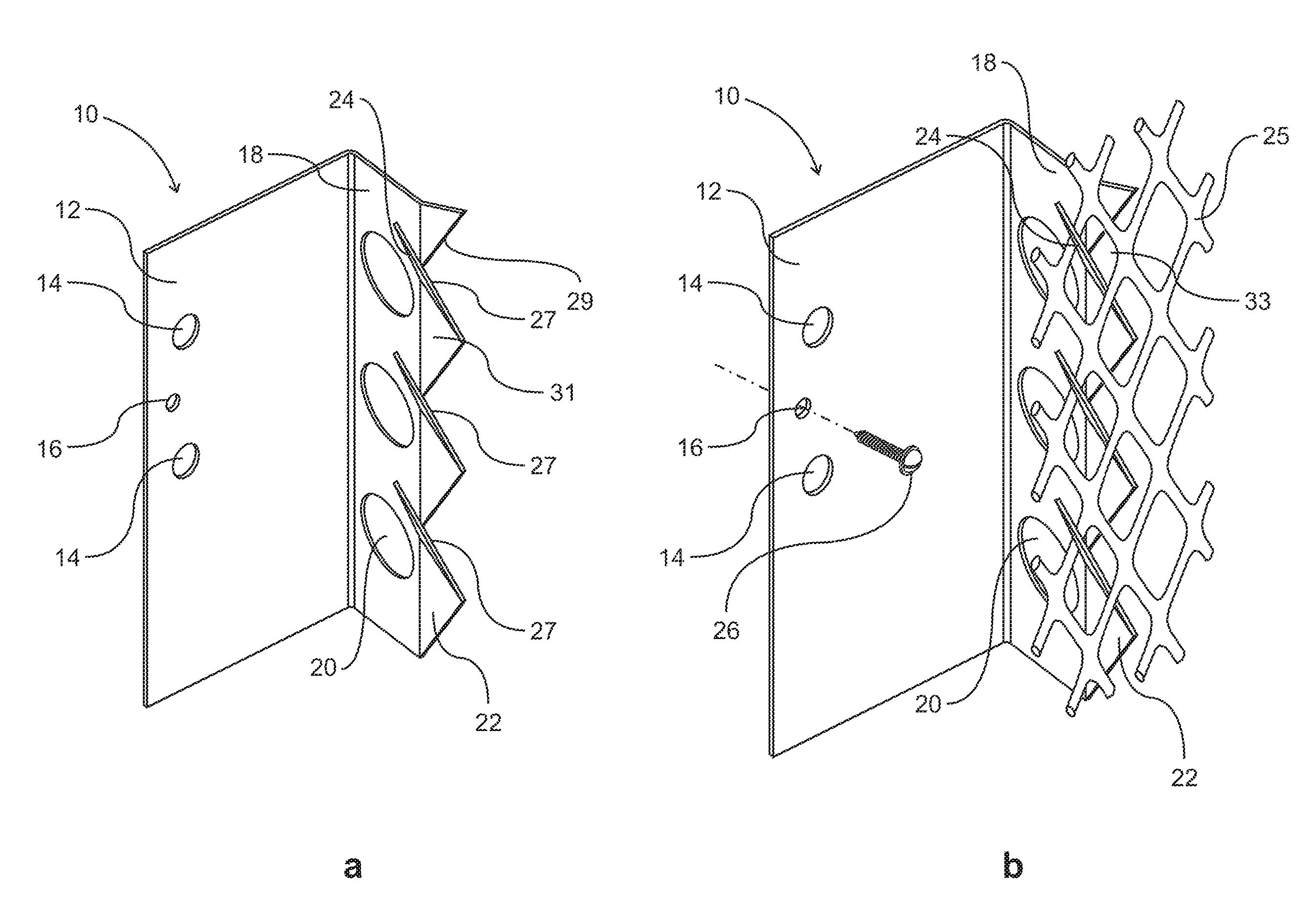
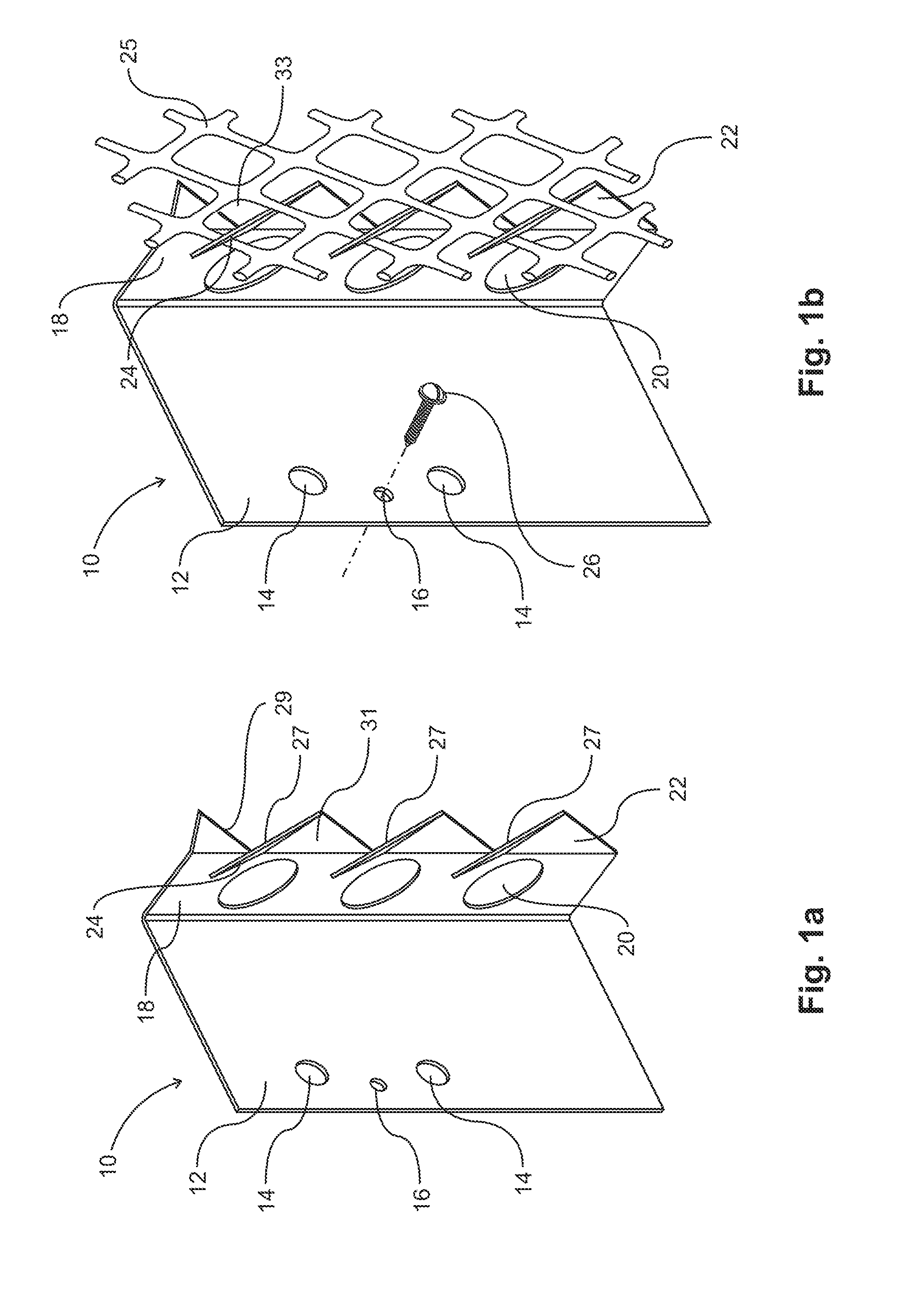
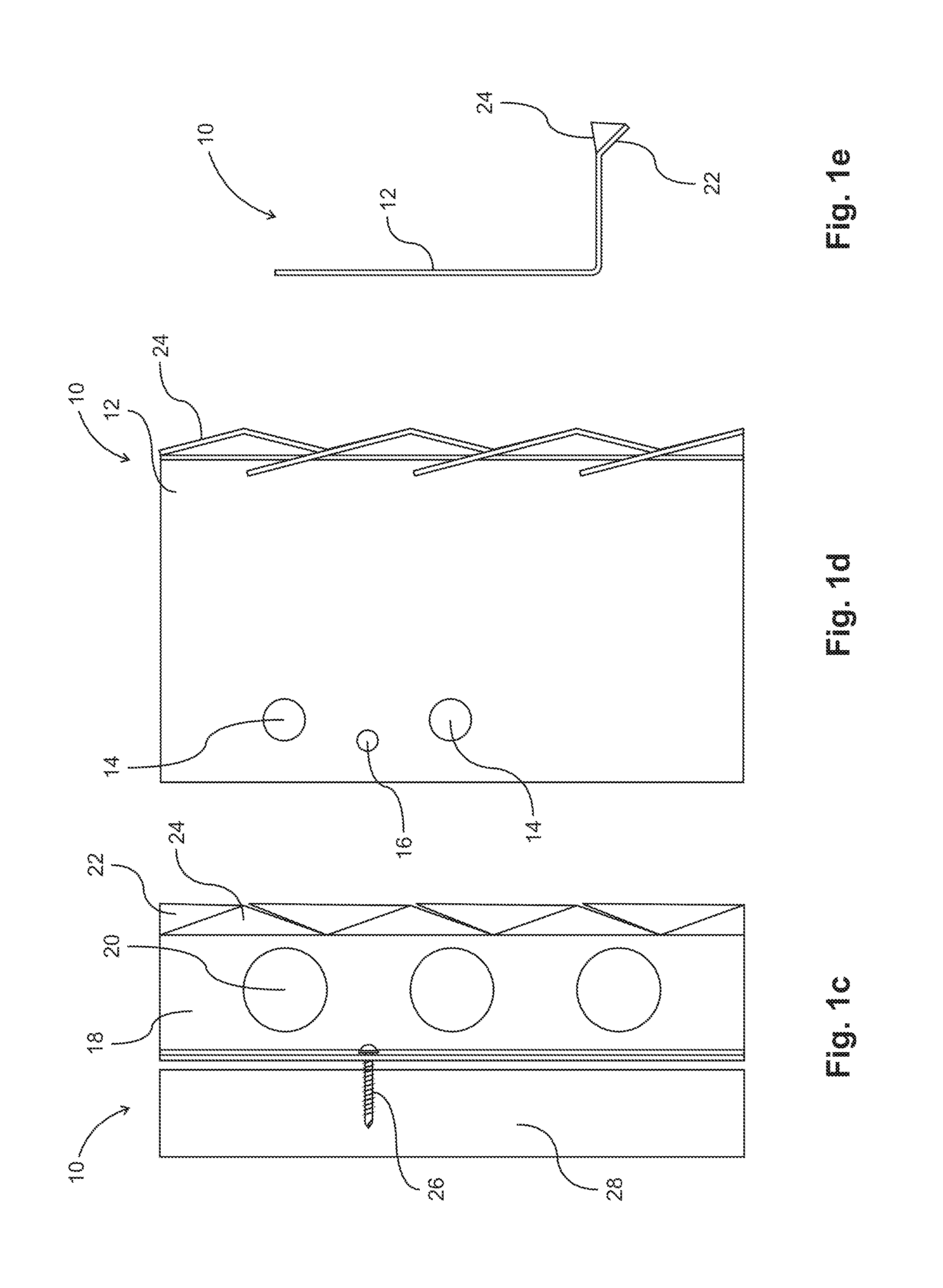
[0120]FIGS. 1a-e depicts an embodiment of an attachment strip 10 having teeth able to secure a lath to the attachment strip without the use of any separate attachment device. The attachment strip 10 has a mounting plate 12 that secures the attachment strip 10 to a wall 28 via a screw 26 that enters the mounting plate 12 via a mounting plate screw hole 16. The mounting plate 12 has additional holes 14 for securing the mounting plate 12 to a wall, as well as keying holes 20 where plaster can seep into and bond the lath 25 to the attachment strip 10. Extending substantially per...


PUM


Abstract

An attachment strip for attaching lath to a wall and a system for attaching lath to a wall with increased water resistive characteristics. The attachment strip has protruding teeth on an attachment plate that holds the lath in place, and a mounting plate that secures the lath furring strip against the wall and framing. In addition, since attachment strip, instead of the lath directly, is secured to the sheathing, fewer mounting devices are needed compared to when a lath is directly secured to a sheathing, where substantially more mounting devices would be needed. Thus in this arrangement, fewer penetrations are created when installing the lath. Additional water resistive features, such insulation layers, and a drainage space surrounded by two water resistive barriers, create space that not only increases insulation, but protects the inner layers of a wall from damage.

Description

FIELD OF THE INVENTION[0001]This invention relates to exterior wall assemblies. In particular, this invention relates to structures for securing lath, insulation, and / or intermediary sheeting in the multi-component construction of exterior walls with the purpose of improving water resistance, improving moisture egress, reducing thermal transfers, adapting wall assemblies to better receive insulation, and reducing labor costs associated with the construction of exterior walls.BACKGROUND OF THE INVENTION[0002]One of the purposes of the present invention is to overcome problems associated with securing lath to walls. In wall construction, plaster is traditionally applied to a flexible lath material. The sheathing material to which the lath is secured is usually lined with a moisture resistive barrier. The current method of fastening lath to sheathing is either with staples, nails or screws. These traditional methods of attaching the metal lath to the sheathing creates multiple penetrat...

Claims


Application Information

Patent Timeline
Patent Type & Authority Applications(United States)
IPC IPC(8): E04F13/21
CPCE04F13/0817E04F13/0803Y10T403/51E04B1/665E04B1/70E04B2/02E04B2/46E04B2002/0232E04C2/043E04F13/22E04F13/24
Inventor BRADY, TODD A.
Owner BRADY TODD A
Why Eureka
Try Eureka