Radio transceiver with improved radar detection

a radio transceiver and radar technology, applied in the field of data networking, can solve the problems of radio signals that interfere with radar reception, access points that are inevitably very high data bandwidth, and cellular base stations, and achieve the effect of reducing the level of first transmitter signal impairmen

Active Publication Date: 2014-05-01
COMS IP HLDG LLC
View PDF0 Cites 53 Cited by
  • Summary
  • Abstract
  • Description
  • Claims
  • Application Information

AI Technical Summary

Benefits of technology

[0024]Embodiments of the invention are applicable to both frequency division duplex (FDD) operation and time division duplex (TDD) operation of the radio link. Performance can be improved with an FDD link using a radar detector co-located with the receiver on the channel on which it is detecting, because the detector can listen for the radar with 100% duty factor. This high-duty factor availability of the radar detector creates a peak-detection capability over time that insures the detector is exposed to the largest radar signal of the time varying channel, mitigating the losses from multipath fading due to channel variations and a rotating radar detection antenna.
[0029]The controller associated with the second transmitter may cause the second transmitter to adjust at least one adjustable parameter associated with the second transmit channel.
[0051]The wireless communications system may further include a cancellation circuit within the first transceiver, wherein the cancellation circuit is coupled to at least the first radar detector; and wherein the cancellation circuit adjusts a signal representative of the output of the first transmitter such that the adjusted signal in combination with a received signal for the first radar detector together result in a reduced level of first transmitter signal impairment to the first radar detector.

Problems solved by technology

However, cellular base stations or WLAN access points inevitably become very high data bandwidth demand points that require continuous connectivity to an optical fiber core network.
Radio signals can interfere with radar reception.
Although effective for high performance communications, FDD frame-based radio operation makes detection of radar signals using conventional methods impossible.
One problem with existing networks is that when the transmitter is transmitting, the high signal level swamps out the receive signals for typical receivers that are located in close proximity to the transmitter, thereby limiting the ability for a radar detector co-located with the transmitter to detect a radar signal.
If a WiFi system operates with a transmit traffic load such that it uses a high duty factor, it can miss radar detections.
It cannot perform radar detection on the transmit channel while the transmitter is transmitting.
The Mohebbi system is also inferior in radio performance because it requires a clear channel available in both directions for two frequencies, which is very difficult to achieve from a frequency planning point of view.
The level of interference measured at the transmitter is uncorrelated to that measured at the receiver simply because there is different propagation from an arbitrarily placed interference source to each side.
If a transceiver must receive at two frequencies to maintain a link, it must find two channels that are relatively free of interference to operate, making it much harder to create a good link; in a probabilistic interference setting, this requirement, at a minimum, squares the difficulty of operation.
Moreover, in the system of Mohebbi these two channels must be clear at both transceivers on either end of the link and for backhaul radios separated by considerable distances this also squares the difficulty of operation because the interference environments at each end of the link are likely quite different.
Thus, the frame-based FDD system has particular challenges for performing radar detection under the various regulatory requirements around the world because, unlike packet-based transmitters such as WiFi radios that can operate at a modest duty factor, the frame-based transmitter is active at high duty factors.
An outage of this length is unacceptable in many applications.
But for wideband devices, as are often found in high-duty-factor links that achieve high throughput, this unduly punishes a system for spreading its channel power over a wider bandwidth, thus reducing its spectral power density.

Method used


Image

  • Radio transceiver with improved radar detection
  • Radio transceiver with improved radar detection
  • Radio transceiver with improved radar detection

Examples


Embodiment Construction

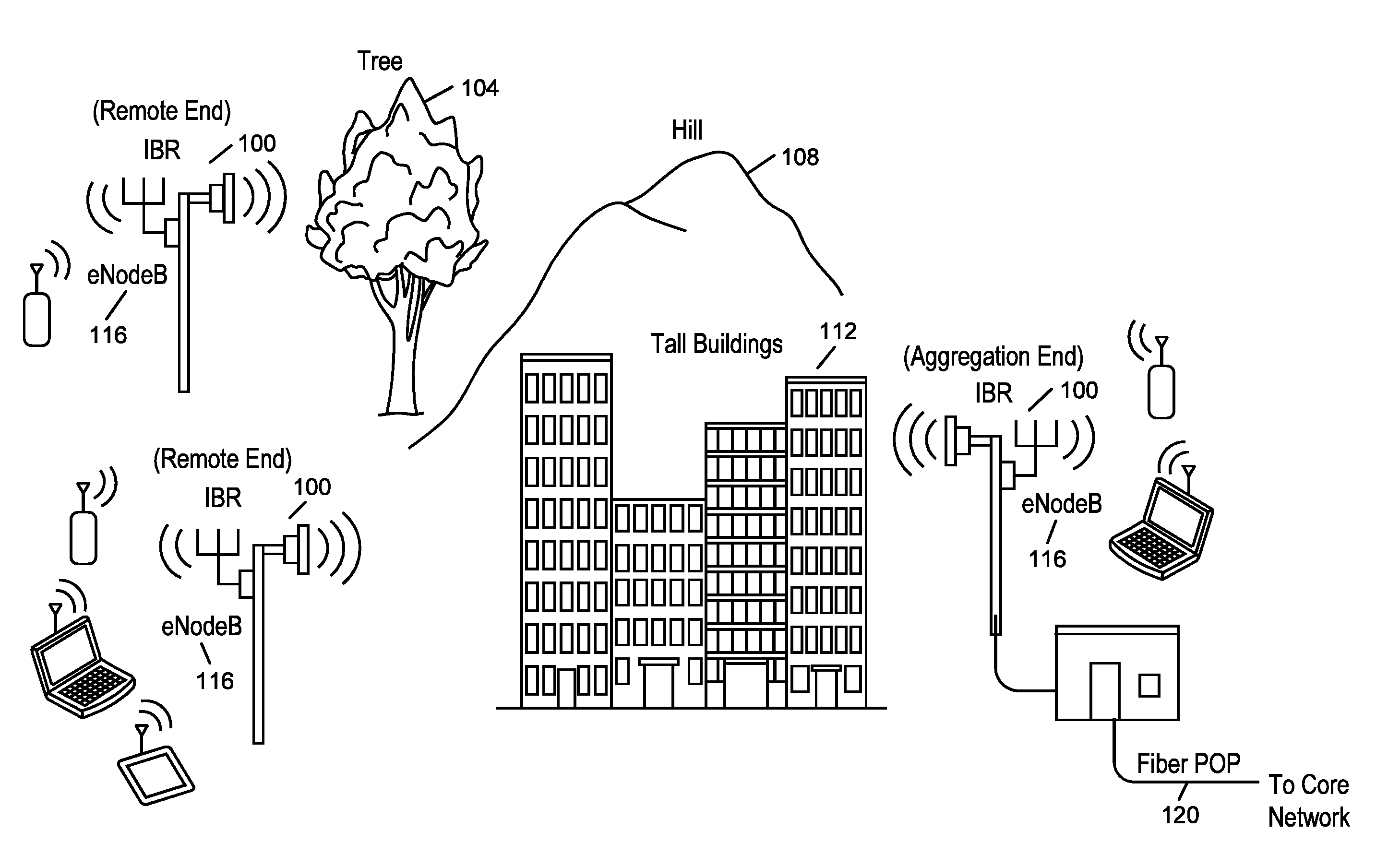
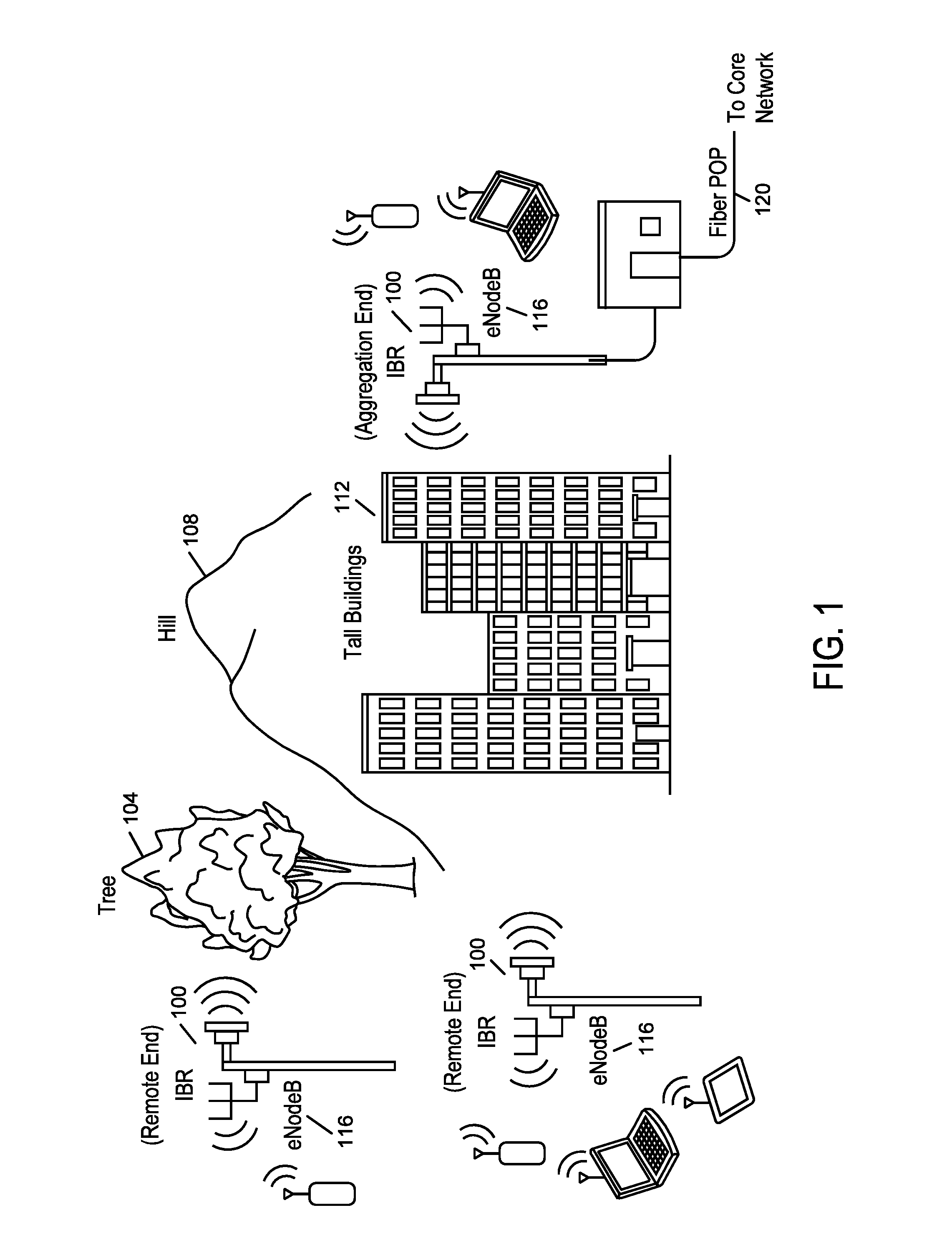
[0098]In a radio system that can have multiple radar detectors, such as a point-to-multipoint and other configurations in the array of backhaul networks, the radar detectors become a shared network resource. Embodiments of the invention make use of the shared resource by operating these detectors cooperatively, or in a coordinated manner, to perform the radar detection function efficiently and provide expanded capability such as channel look ahead, extended detection bandwidth, and more reliable detectability through location, angle, and antenna diversity.

[0099]Embodiments of the invention perform radar detection at the receiver side for the transmitter that occupies the channel at the same time the transmitter is sending. In some embodiments of the invention, the detector relays the results over a separate communications channel. This separate communications channel may be the part of an FDD link that operates in the other direction. The communication may also be indirect. For exam...


PUM


Abstract

A radar detector is used with a radio link, the radio link characterized by high duty factor operation of a radio transmitter. The radar detector is located a sufficient distance from the radio transmitter that the radar detector is not overwhelmed by the radio transmission signal in that channel and can detect sufficiently low level radar signals to ascertain potential radio interference at the radar from said radio transmitter. The results of the radar detection are communicated to the transmitter in a way that impacts the transmitter's use of the sensed channel. This communication can occur reactively when a radar detection is achieved (the absence of which indicates no radar has been detected) and / or can be a periodic or event-driven indication that the channel is available for operation (the information expiring if the result is not refreshed).

Description

CROSS-REFERENCE TO RELATED APPLICATIONS[0001]The present application is a continuation-in-part application of U.S. patent application Ser. No. 13 / 645,472, filed on Oct. 4, 2012, which claims priority to U.S. Pat. No. 8,311,023 and U.S. Pat. No. 8,238,318, the disclosures of which are hereby incorporated herein by reference in their entirety.[0002]The present application also claims priority to U.S. Provisional Patent Application Ser. No. 61 / 857,661, filed Jul. 23, 2013, entitled “Intelligent Radio transceiver with Improved Radar Detection Capability”, the entirety of which is hereby incorporated by reference.[0003]The present application is also related to U.S. patent application Ser. No. 13 / 898,429, filed May 20, 2013 and U.S. Pat. No. 8,467,363, the disclosures of which are hereby incorporated herein by reference in their entirety.[0004]The present application is also related to U.S. patent application Ser. No. 13 / 767,796, filed Feb. 14, 2013 and U.S. Pat. No. 8,422,540, the discl...

Claims


Application Information

Patent Timeline
Patent Type & Authority Applications(United States)
IPC IPC(8): H04W76/02
CPCH04K3/224H04B7/04H04W76/026H01Q21/24H01Q25/005H04W88/02H04L1/0009H01Q25/00H04K3/226H04K2203/32H04K3/822H01Q1/246H04W52/367H04L1/1607H04L2025/03414H04L1/0003H04L27/265H01Q21/29H04K2203/36H04K3/28H04W16/14H04W72/082H04W72/541
Inventor FISCHER, JEFFREYGANDHAM, KISHORENEGUS, KEVIN J.
Owner COMS IP HLDG LLC
Why Eureka
Try Eureka