
Steam cracking processes

a technology of steam cracking and process, applied in the direction of thermal non-catalytic cracking, pressure chemical process, organic chemistry, etc., can solve the problems of heavy liquid phase hydrocarbon components, serious impact on heat transfer process, and easy formation of cok

Active Publication Date: 2014-05-01
CHINA PETROCHEMICAL CORP +1
View PDF3 Cites 9 Cited by
  • Summary
  • Abstract
  • Description
  • Claims
  • Application Information

AI Technical Summary

Benefits of technology

The present patent provides a method for reducing coking of monoolefins in a cracking furnace. The method involves mixing the monoolefin-containing stream with steam and / or hydrogen to slow down the formation of coke and reduce the amount of monoolefins in the gas phase. This helps to stabilize the operation of the cracking furnace and increase the yield of desired products. Additionally, the method allows for the efficient utilization of high-temperature heat and reduces the formation of coke in the quench apparatus, resulting in a higher product yield. The monoolefin-containing material can be a hydrocarbon stream with a certain amount of 1-butene and 2-butene, which can co-crack with the liquid feed stock and the products of the first cracking reaction to increase the yield of butadiene.

Problems solved by technology

When liquid raw materials such as naphtha, diesel, hydrogenated cracking residue, etc. are used, a vaporization process exists in the convection section in the heating process, wherein if the raw material contains olefins, then at the beginning of the vaporization process, a high content of olefins in the gas phase would easily cause formation of coke, and when the vaporization process is to be ended, hydrocarbon components in the liquid phase would be so heavy that coke is also easily formed.
In case severe coke is formed in the convection section of the cracking furnace, not only the heat transfer process would be seriously affected, but the pressure drop therein would also be rapidly increased, which would reduce the yield in the cracking furnace.
Once the content of olefins is too high, subsequent problems would be brought about, such as the formation of coke in the convection section of the cracking furnace and great decrease in the operation cycle of the cracking furnace, whereby causing maintenance shutdown of the cracking furnace.
Moreover, pipe lines are unnecessary to be replaced in the switch between raw materials.
In the prior art, there is limited disclosure relating to the process of feeding olefins (a monoolefin-containing stream) as part of the feed stock into the cracking furnace for steam cracking, not to mention eliminating formation of coke when olefins are injected into the cracking furnace as part of the feed stock.

Method used

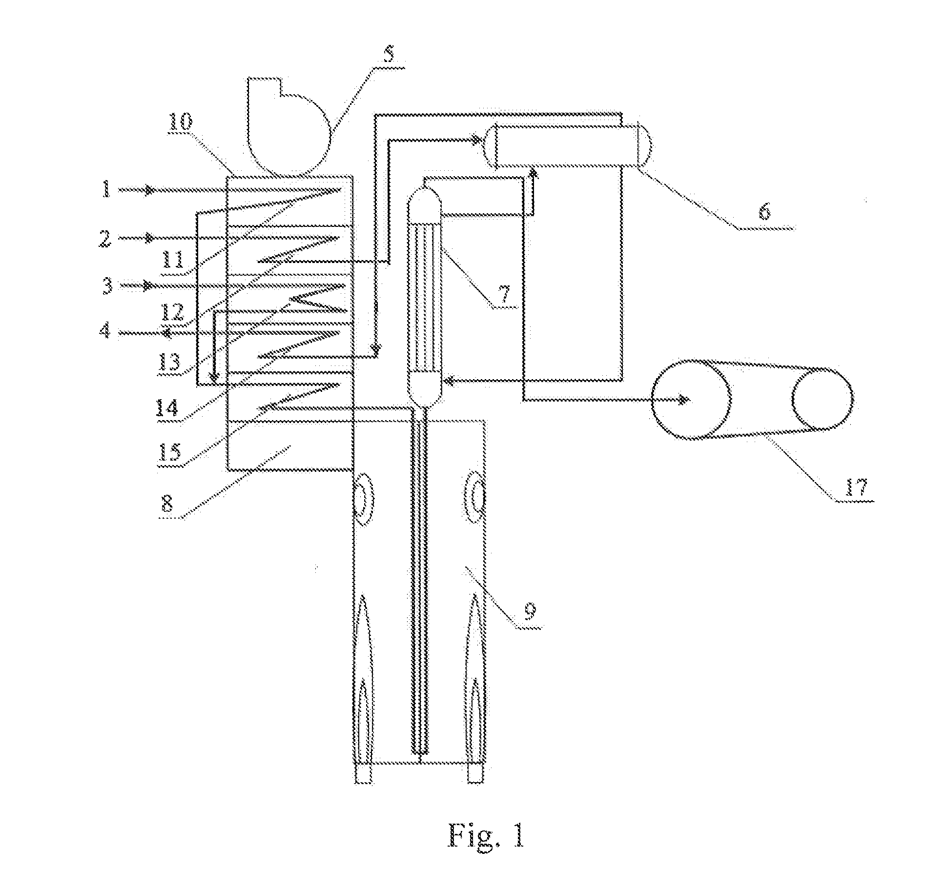

Image

  • Steam cracking processes
  • Steam cracking processes
  • Steam cracking processes

Examples


example 1

[0111]This example is used to explain the steam cracking process provided in the present disclosure,

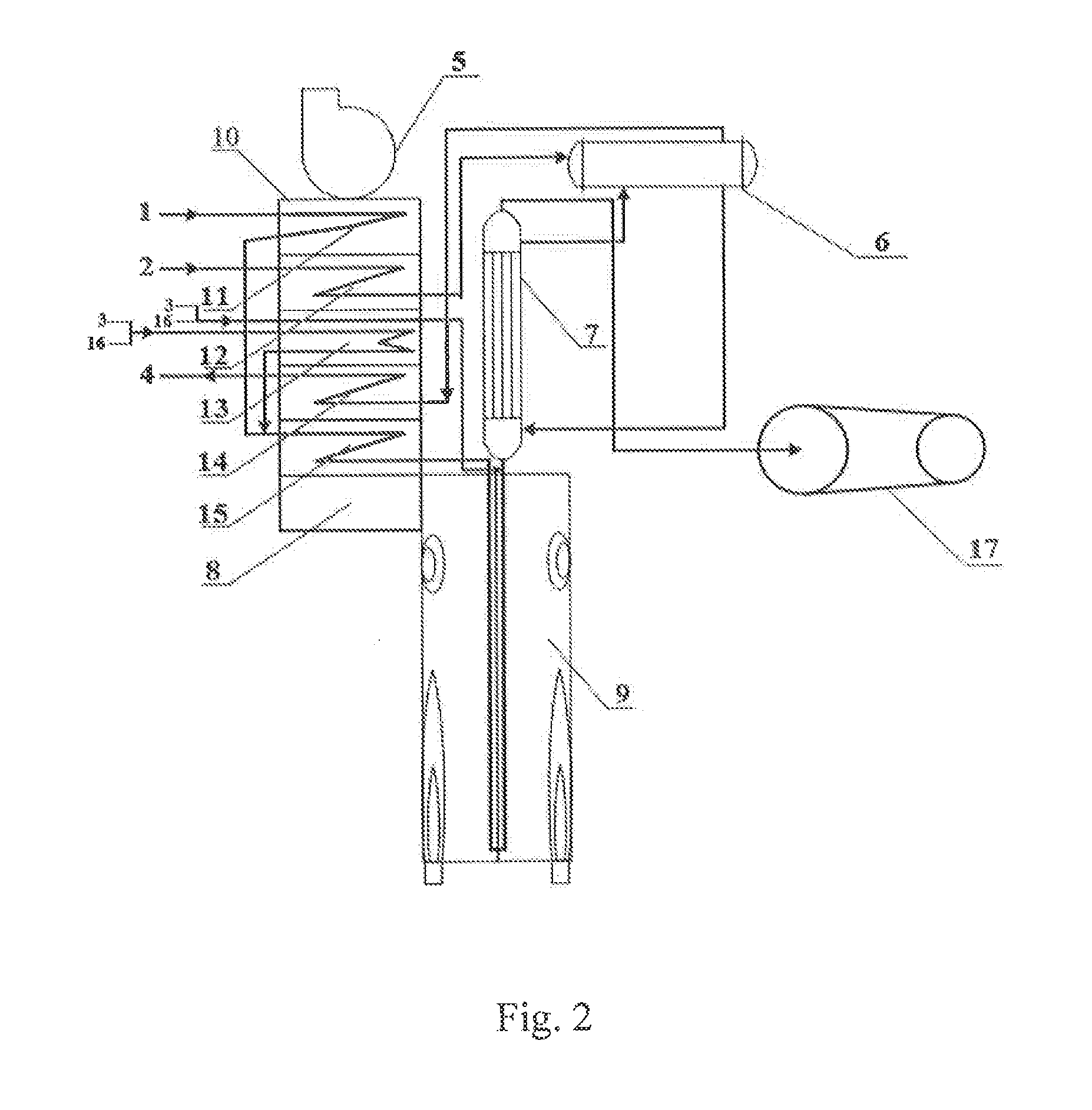
[0112]The cracking apparatus as shown in FIG. 2 is adopted for the cracking reaction. The specific process comprises:

[0113]Naphtha 1 of 60° C. (see Table 1 for the corresponding parameters) is preheated in the material preheating segment 11, and simultaneously a first stream composed of steam 3 and a monoolefin-containing (mixed C4 olefins) stream 16 with the composition as shown in Table 2 is preheated in the diluted steam superheating segment 13. After that, the preheated naphtha and the preheated first stream are mixed and the resulting feed stock mixture is heated in the hybrid heating segment 15 before entering into the radiant section 9 for cracking reaction. In addition, a second stream composed of steam 3 and mixed C4 olefins 16 with the composition as shown in Table 2 is preheated in the diluted steam superheating segment 13 to obtain a first mixture (the monoolefin-containin...

example 2

[0119]The process of Example 1 (see FIG. 2) is adopted to carry out the steam cracking reaction. But the feeding rate of naphtha is 40,860 kg / h, and in the first stream the injection rate of steam is 22,700 kg / h and the feeding rate of the mixed C4 olefins is 4,540 kg / h. In the second stream, the injection rate of steam is 2,270 kg / h and the feeding rate of the mixed C4 olefins is 1,362 kg / h. The temperatures of the preheated first and second streams are respectively 530° C. and 560° C. The crossover temperature (XOT) is 596° C. and the temperature at the outlet of the cracking furnace (COT) is 830° C. The cracking reaction time in the radiant section 9 is 0.3 s. Other process parameters of the cracking furnace and transfer line exchange 7 are listed in Table 7. The cracked gases are separated and analyzed and the composition thereof is shown as in Table 8.

TABLE 7TemperaturePressureFlow (kg / h)(° C.)(kPa-g)Feed stockInitial stage toInitialFinalInitialFinalOperational stagefinal stage...

example 3

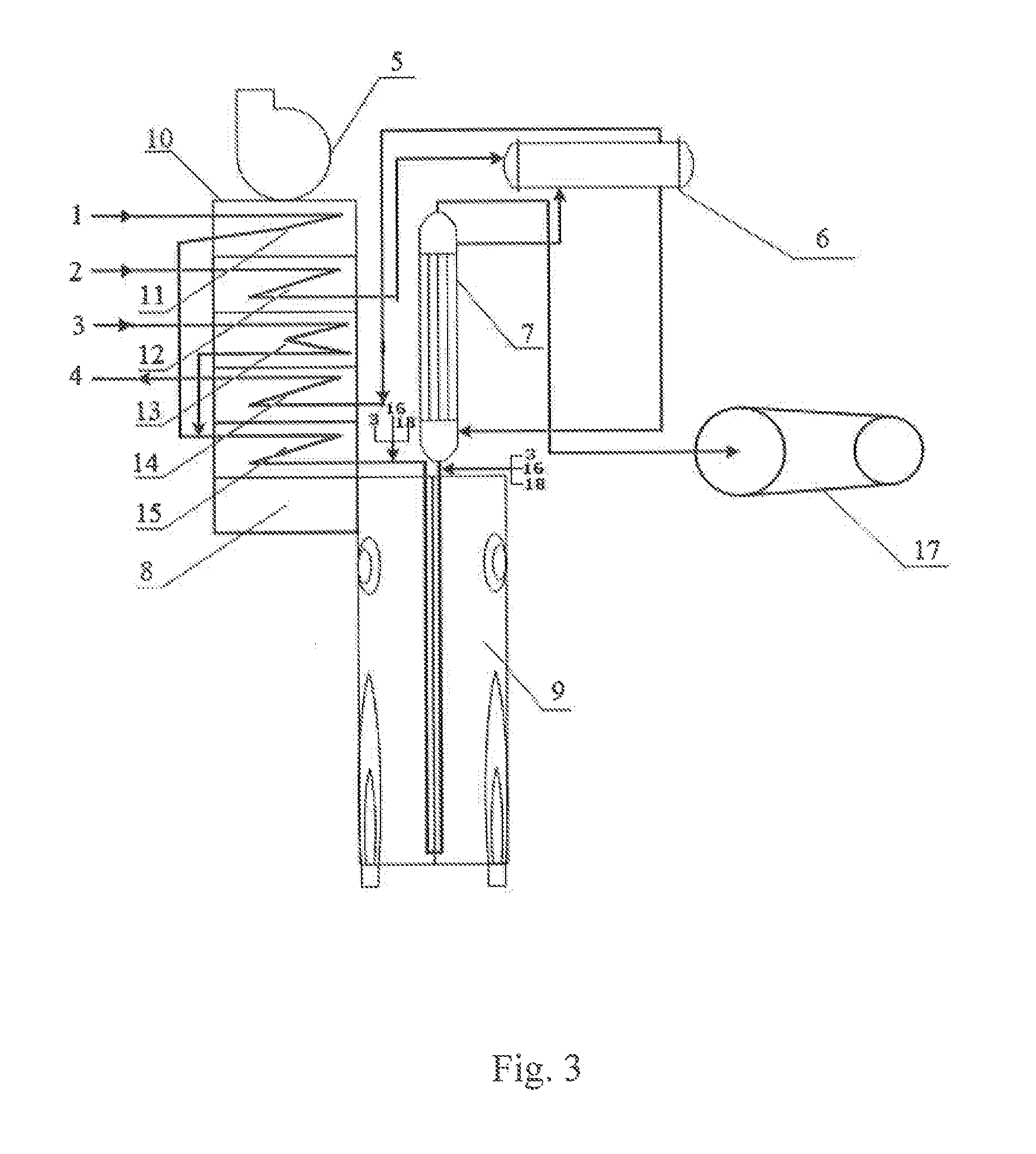
[0120]The cracking furnace as shown in FIG. 3 is adopted for the cracking reaction. The specific process comprises:

[0121]The C4 olefins 16 with the composition as shown in Table 2 are added into the evaporator for vaporization and mixed C4 olefins of 180° C. are obtained. The mixed C4 olefins are then mixed with hydrogen 18 and steam 3 to obtain a first mixture, which is divided into a first stream and a second stream for the cracking reaction of the present disclosure.

[0122]Naphtha 1 of 60° C. (see Table 1 for the corresponding parameters) is preheated in the material preheating segment 11, and steam 3 is simultaneously preheated in the diluted steam superheating segment 13. The preheated naphtha and the preheated steam are mixed and the resulting feed stock mixture is preheated to the crossover temperature in the hybrid heating segment 15 before being mixed with the first stream of the first mixture. The mixed resultant is then injected into the radiant section 9 for cracking reac...


PUM

PropertyMeasurementUnit
temperatureaaaaaaaaaa

Abstract

The present disclosure provides a steam cracking process, comprising heating a liquid feed stock in a convection section of a cracking furnace and subsequently conveying the material to a radiant section of the cracking furnace for cracking reaction therein, wherein a monoolefin-containing stream is conveyed to the cracking furnace for cracking reaction through at least one of modes A to C.

Description

[0001]This application claims benefit of priority under 35 U.S.C. §119 to Chinese Patent Application Nos. CN 2012104198411, CN 201210420746.9, and CN 201210420748.8, filed Oct. 29, 2012, the contents of which are also incorporated herein by reference.TECHNICAL FIELD[0002]The present disclosure relates to a steam cracking process.TECHNICAL BACKGROUND[0003]Light olefins such as ethylene, propylene and butadiene are important basic raw materials in the petrochemical industry and are mainly produced by the cracking furnace steam cracking process at present. Statistics shows that about 99% of ethylene, more than 50% of propylene and more than 90% of butadiene in the world are produced by the above process.[0004]A process unit based on the cracking furnace steam cracking process and the downstream cryogenic separation process as essential technologies is called an ethylene plant. A cracking furnace comprising a convection section and a radiant section is the key apparatus of an ethylene p...

Claims


Application Information

Patent Timeline
Patent Type & Authority Applications(United States)
IPC IPC(8): C07C4/04
CPCC07C4/04C10G9/36C10G2300/1088C10G2300/1092B01J19/2415B01J19/0013B01J2219/00081B01J2219/00105B01J2219/00157B01J2219/00159C07C7/00C07C9/16C07C9/15B01J19/24C10G47/22C10G75/00B01J3/00
Inventor WANG, GUOQINGZHANG, LIJUNZHANG, YONGGANGLIU, JUNJIEDU, ZHIGUOZHOU, XIANGFENGLI, WEIZHOU, CONG
Owner CHINA PETROCHEMICAL CORP
Learn More