Camera objective and camera system

a camera and objective technology, applied in the field of camera objective and camera system, can solve the problems of disturbing effects, esthetically unwanted effects, and affect the accuracy of triangulation calculation, and achieve the effect of improving the accuracy of depth value determination

Active Publication Date: 2014-05-08
ARNOLD & RICHTER CINE TECH GMBH & CO BETRIEBS KG
View PDF1 Cites 4 Cited by
  • Summary
  • Abstract
  • Description
  • Claims
  • Application Information

AI Technical Summary

Benefits of technology

[0035]In accordance with a further advantageous embodiment, the camera system furthermore has a lighting apparatus for lighting objects to be taken with a spatially modulated, in particular a spatially periodically modulated lighting radiation of the second spectral range. The accuracy of the depth value determination can thereby in particular be improved with objects having only a small texture since an additional texture is imposed on the objects by a modulated or structured lighting.

Problems solved by technology

This impairs the accuracy of the triangulation calculation.
On the taking of images while using coded apertures, however, the influencing of the figure of confusion, which is desired per se for the acquisition of the depth information, by objects not located in the focusing plane can result in esthetically unwanted effects.
However, these effects are disturbing at least during the taking on the use of an electronic viewfinder (direct reproduction of the taken image).

Method used


Image

  • Camera objective and camera system
  • Camera objective and camera system
  • Camera objective and camera system

Examples


first embodiment

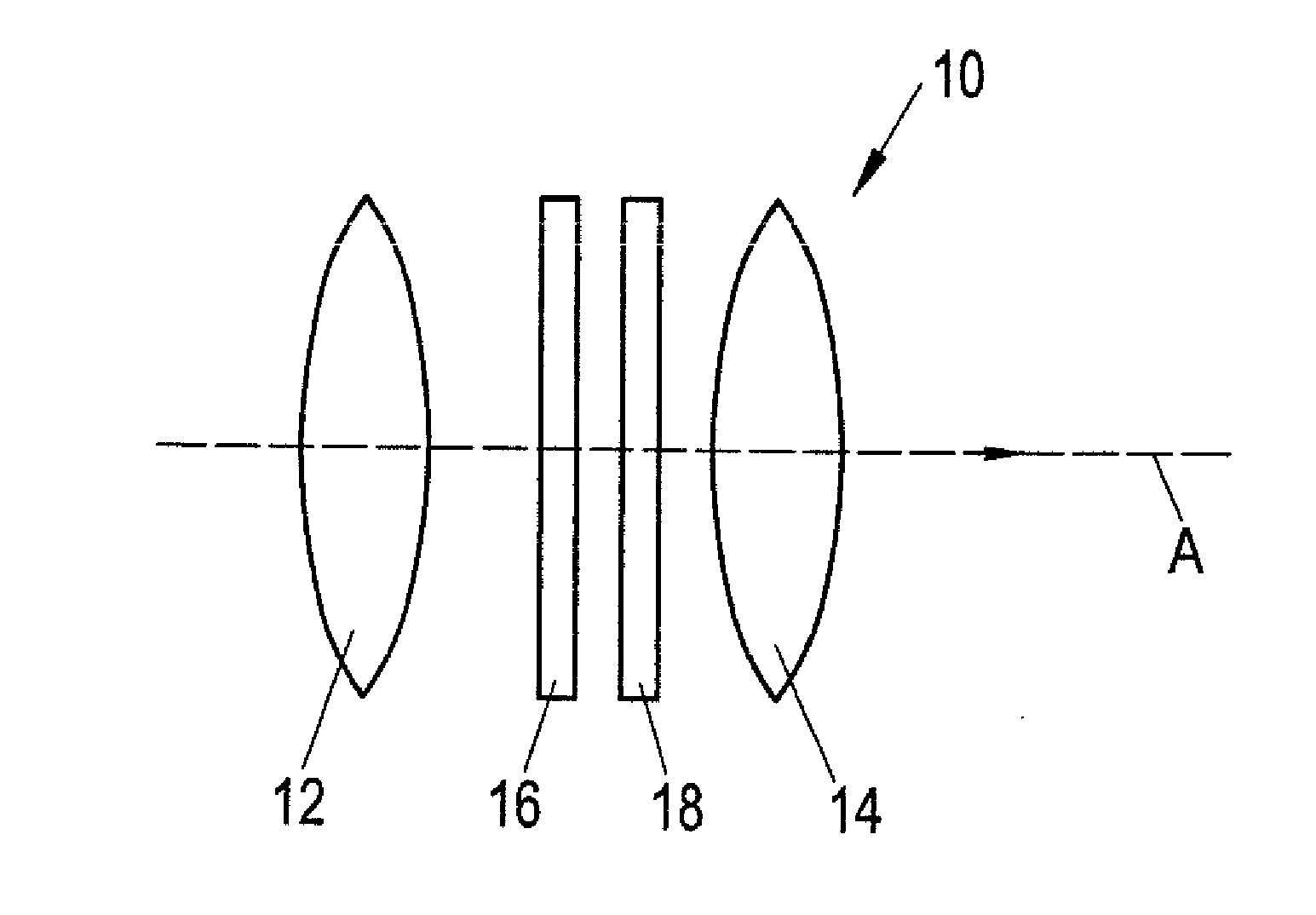
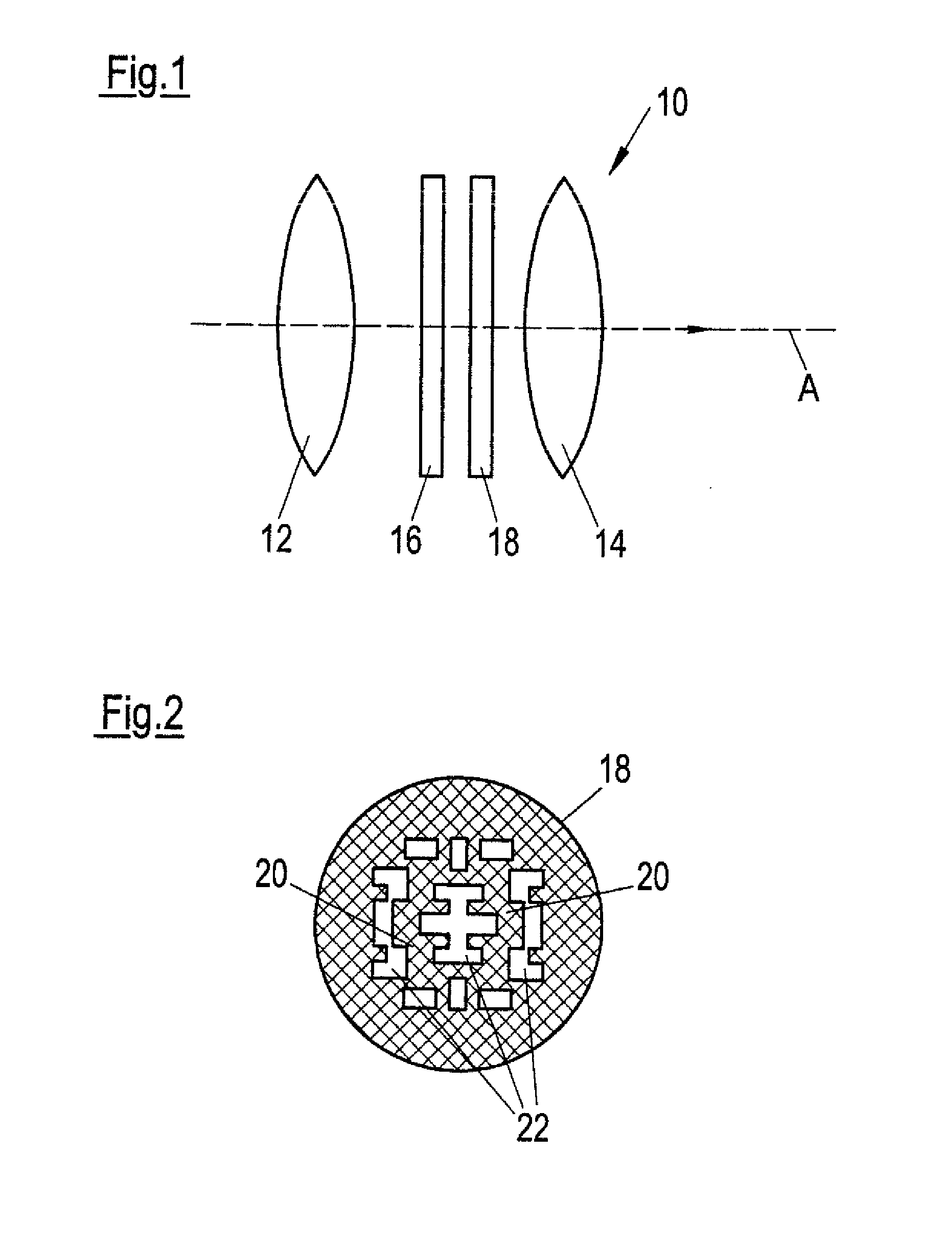
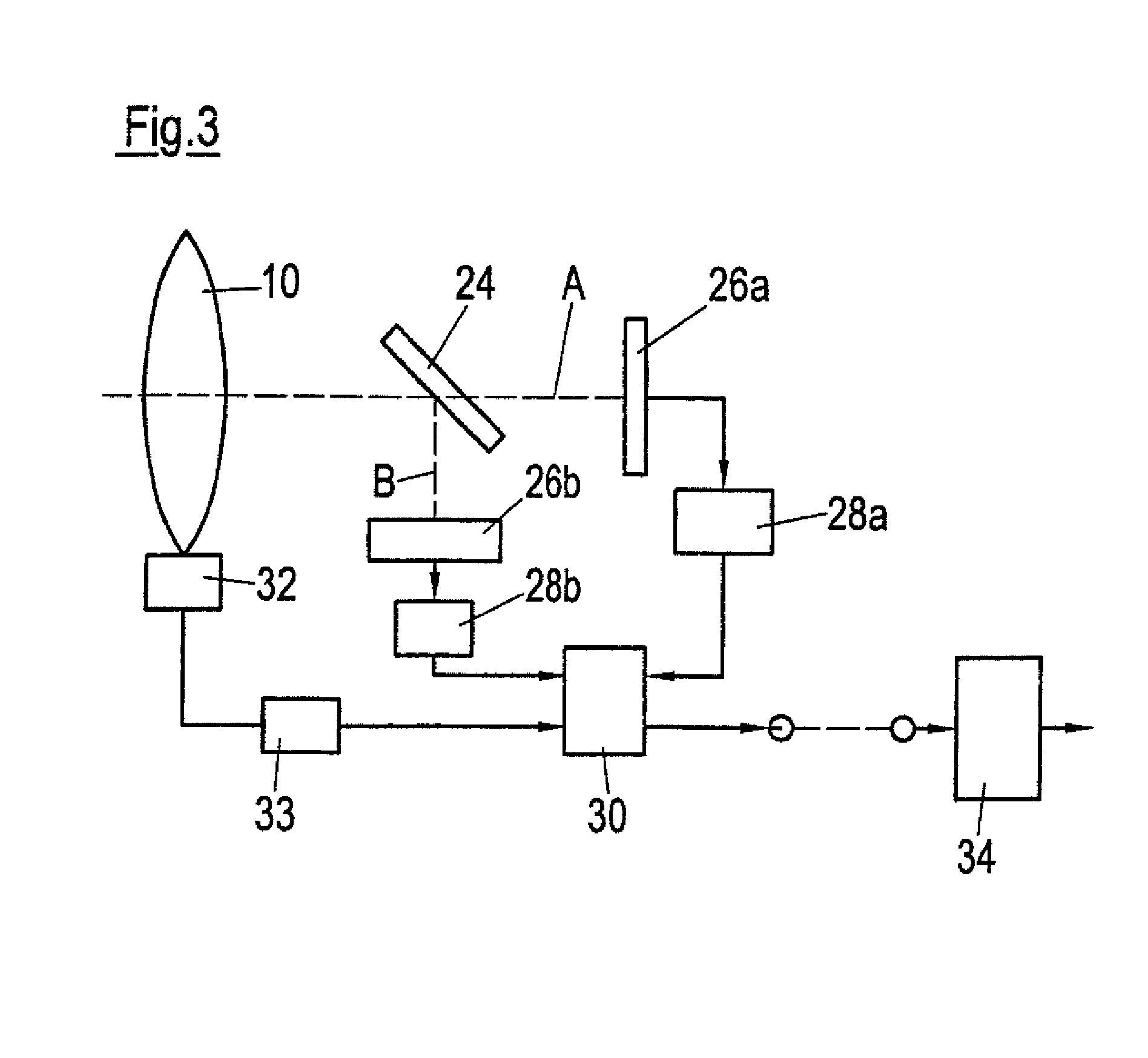
[0046]A camera system in accordance with the invention in accordance with a first embodiment includes, in accordance with FIG. 3, a camera objective 10 arranged on the optical axis A. A sensor 26a which is sensitive for visible light is likewise located on the optical axis. In this respect, it can, for example, be a conventional CMOS sensor which has sensor elements which are sensitive to red, green and blue light respectively due to a suitable filter coating.

[0047]A beam splitter 24 which permanently transmits the visible light to the sensor 26a, whereas the infrared radiation is permanently reflected in the direction of a sensor 26b, is provided at an angle of for example 45° to the optical axis A between the camera objective 10 and the sensor 26a. The sensor 26b is arranged on a secondary axis B perpendicular to the optical axis A, for example, and is, for example, a CMOS sensor sensitive for infrared radiation.

[0048]FIG. 4 shows a respective part section of the sensors 26a and 2...

third embodiment

[0058]A camera system in accordance with a third embodiment includes, in accordance with FIG. 6, a camera objective 10 in accordance with the invention which preferably likewise has a data memory 32. A single sensor 26 is arranged on the optical axis A behind the camera objective 10 and has a plurality of sensor elements which are sensitive either in the visual spectral range or in the infrared spectral range.

[0059]A part section of the sensor 26 is shown in FIG. 7. A matrix of 2×2 sensor elements 36a to 36d is repeated periodically over the surface of the sensor 26. Respective different filters are applied to the sensor elements 36a to 36c so that the sensor element 36a is sensitive for green light, the sensor element 36b for blue light and the sensor element 36c for red light. A fourth sensor element 36d is only sensitive for infrared radiation.

[0060]In accordance with FIG. 6, the received signals generated by the sensor 26 are transmitted to a signal processing unit 28 in which t...


PUM


Abstract

A camera objective for a camera includes a mask having a plurality of masking sections which are permeable for radiation of a first spectral range and are impermeable for radiation of a second spectral range different from the first spectral range. A camera system includes a digital camera for taking images. The camera system includes such a camera objective and an optoelectronic sensor arrangement having a plurality of sensor elements for generating exposure-dependent received signals which form a respective image. The plurality of sensor elements includes a first group of sensor elements for generating received signals in dependence only on radiation of the first spectral range and a second group of sensor elements for generating received signals in dependence on radiation of the second spectral range.

Description

CROSS-REFERENCE TO RELATED APPLICATIONS[0001]This application is a continuation of U.S. patent application Ser. No. 13 / 154,573 filed Jun. 7, 2011, which claims priority of German Patent Application DE 10 2010 023 344.7 filed Jun. 10, 2010.FIELD OF THE INVENTION[0002]The present invention relates to a camera objective for a camera having a mask comprising a plurality of masking sections. The invention further relates to a camera system having a digital camera, in particular a digital motion picture camera, for taking images.BACKGROUND OF THE INVENTION[0003]It is desirable both with still cameras and with moving image cameras also to acquire information on the depth of field or depth information of the motif taken in addition to the two-dimensional image information. The availability of depth information is sensible for various applications. Support for or automation of the focusing process of the objective and applications in the field of visual effects, which are produced digitally ...

Claims


Application Information

Patent Timeline
Patent Type & Authority Applications(United States)
IPC IPC(8): G02B5/22G02B5/20
CPCG02B5/208G02B5/22G03B35/08G06T2207/10004G03B11/00G06T7/571G02B27/0075G02B5/201G02B2207/129H04N13/207H04N13/271H04N23/67H04N23/11H04N25/131H04N25/135H04N25/134G03B11/04
Inventor STEURER, JOHANNES
Owner ARNOLD & RICHTER CINE TECH GMBH & CO BETRIEBS KG
Why Eureka
Try Eureka