Interface Devices, Systems and Methods for Multimodal Probes

a multi-modal, interface device technology, applied in the field of intravascular ultrasound (ivus) and optical coherence tomography, can solve problems such as more difficult interpretation of data, and achieve the effect of reducing common mode nois

Active Publication Date: 2014-05-22
LIGHTLAB IMAGING
View PDF7 Cites 75 Cited by
  • Summary
  • Abstract
  • Description
  • Claims
  • Application Information

AI Technical Summary

Benefits of technology

[0020]In one embodiment, the second rotatable optical fiber segment and the fiber optic rotary joint are at least partially disposed in the elongate cavity and one or more of the conductive windings are annularly disposed around the fiber optic rotary joint. In one embodiment, the first conductive windings are stationary windings and the stationary optical fiber and stationary windings are connected to the stator. In one embodiment, the second conductive windings are rotatable windings and the rotary optical fiber segment and rotatable windings are connected to the rotor. In one embodiment, stationary windings and the stationary optical fiber are connected to the stator. In one embodiment, the rotary rotatable windings and the rotary optical fiber segment are connected to the rotor. In one embodiment, a ratio of a number of turns in the first conductive winding to a number of turns in the second conductive winding ranges from about 0.25 to about 4. In one embodiment, the ratio is specified to adjust for impedance mismatch or increase the signal return voltage. In one embodiment, a center tap connection is made between the stationary windings to reduce common mode noise. In one embodiment the stator comprises an outer surface wherein the outer surface extends to cover the first gap. In one embodiment a portion of the outer surface comprises an EMI shielding material.

Problems solved by technology

Unfortunately, IVUS images are typically of a lower resolution, which can make interpreting them more challenging.

Method used


Image

  • Interface Devices, Systems and Methods for Multimodal Probes
  • Interface Devices, Systems and Methods for Multimodal Probes
  • Interface Devices, Systems and Methods for Multimodal Probes

Examples


embodiment

Rotary Joint Embodiment

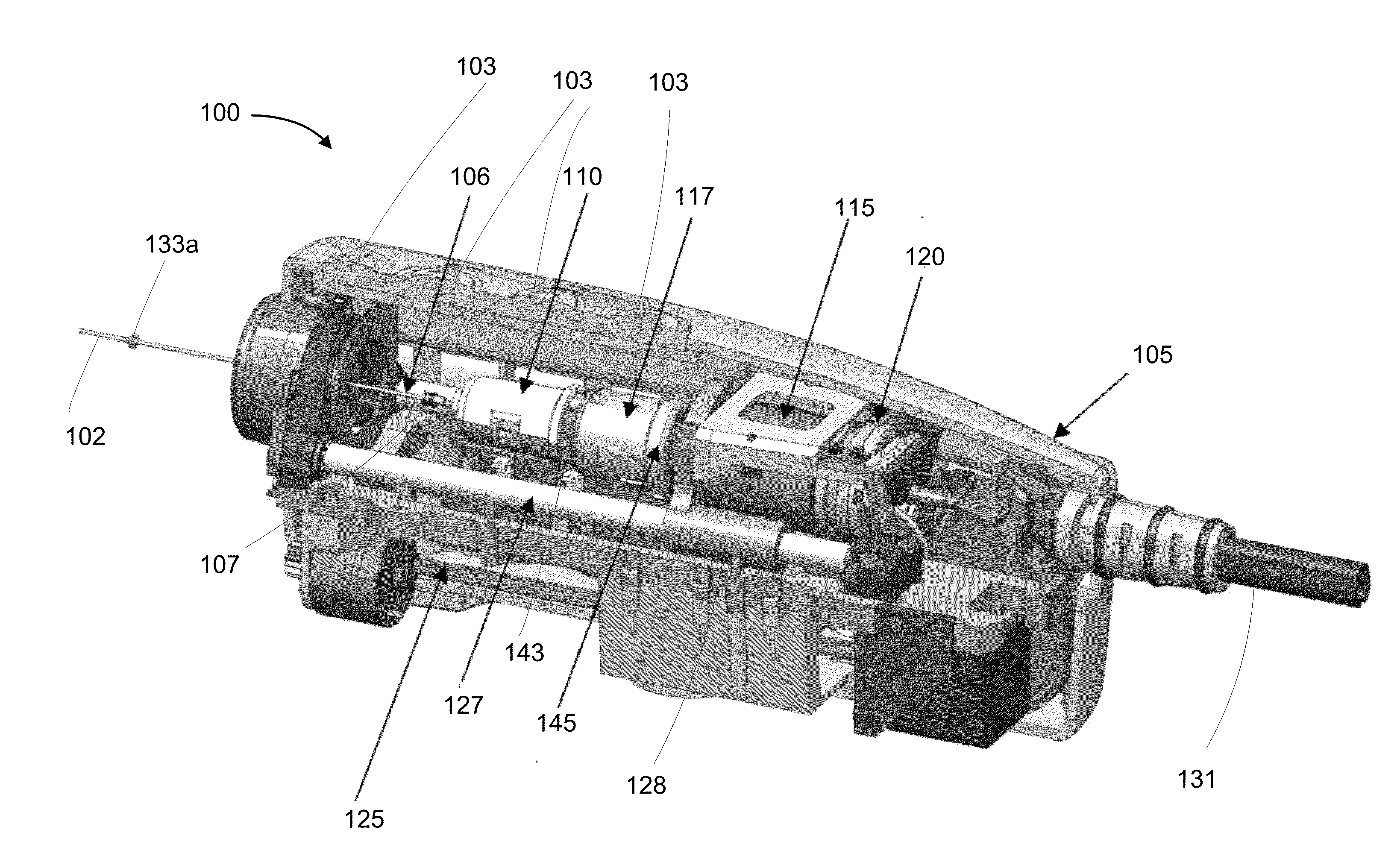
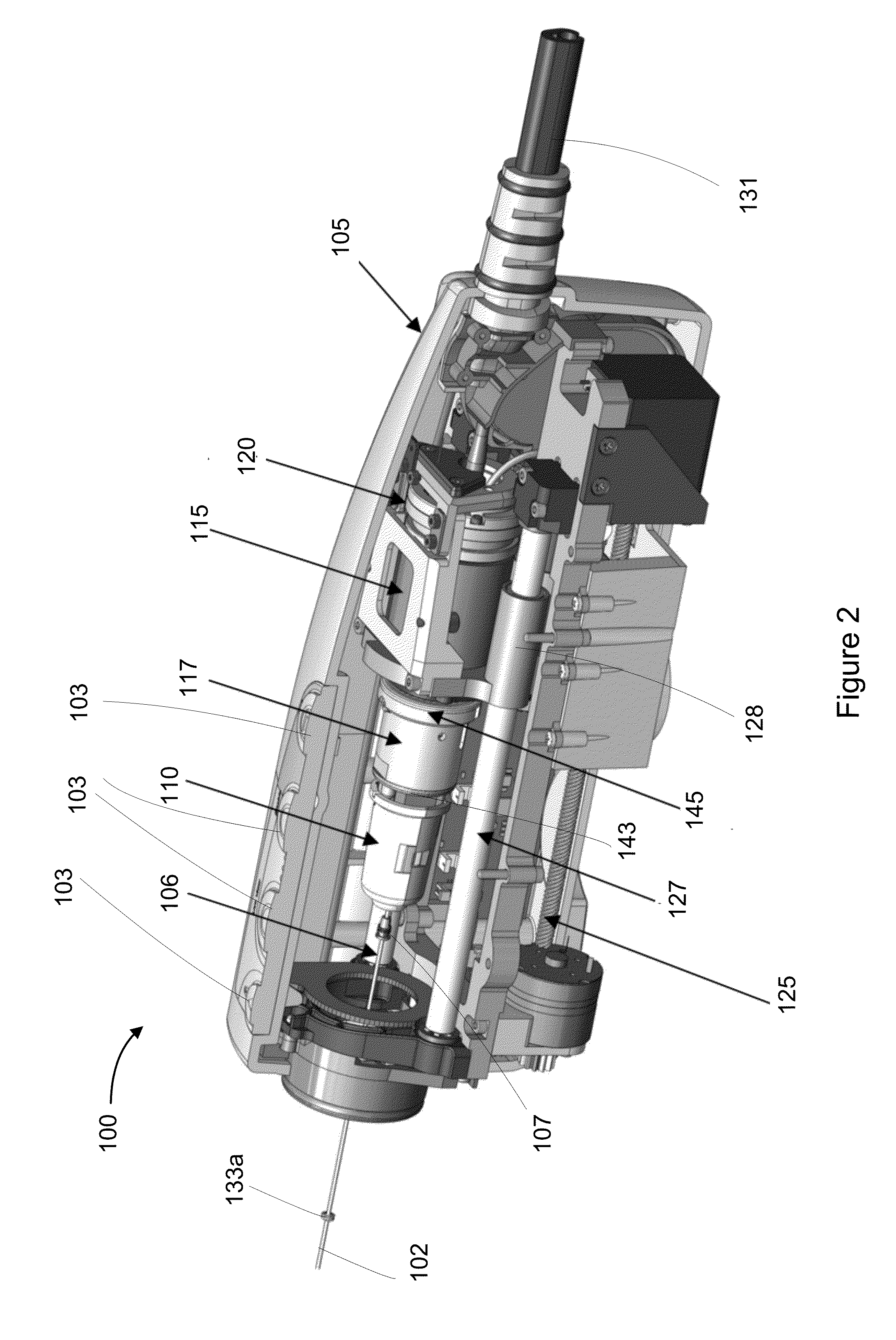
[0084]One or more rotary joints are used to couple two rotating signal transmission lines (optical fiber and plurality of coiled conductors such as wires) within the probe to stationary transmission lines within the PIU. In one embodiment, each rotary joint is a contactless joint because it is configured to couple an optical signal over an air gap or an electrical signal over an air gap. A fiber optic rotary joint is configured such that the optical fiber portion of the joint is coaxial with the axis of rotation in one embodiment. This in turn requires the electrical rotary joint to have a central core which defines a cavity, channel or opening to allow passage of an optical fiber or otherwise define an optical path. Additionally, because both rotary joints have a rotating and stationary part, the central core is sized and otherwise configured to allow for various structural elements to link rotating and non-rotating elements.

[0085]An embodiment of a combinati...


PUM


Abstract

In one aspect, the invention relates to one or more rotatable elements and one or more stationary element such that the elements are arranged along a common axis of rotation co-linear with or substantially parallel to an optical path. The optical path is a portion of a sample arm of an interferometer. Further, the rotatable and stationary elements are configured to couple electrical signals and optical signals between a data collection probe and an interface unit or other component of an imaging system. In one embodiment, the data collection probe is a combination ultrasound and OCT probe. In one aspect, the invention relates to a rotary joint in which the optical fiber and a fiber optic rotary joint lie in the center of one or more conductive elements of an electrical rotary joint which are annularly disposed around one or both of the optical fiber and optical rotary joint.

Description

CROSS-REFERENCE TO RELATED APPLICATIONS[0001]This application claims priority to and the benefit of U.S. Patent Provisional Patent Application No. 61 / 727,997, filed on Nov. 19, 2012, U.S. Provisional Patent Application 61 / 728,006, filed on Nov. 19, 2012, and U.S. Patent Application entitled “Multimodal Imaging Systems, Probes, and Methods” and having Attorney Docket No. LLI-036 filed on Feb. 4, 2013, the entire disclosures of each of which are herein incorporated by reference.FIELD OF THE INVENTION[0002]The invention relates generally to the field of intravascular ultrasound (IVUS) and optical coherence tomography (OCT), and more specifically to OCT and IVUS combination data collection probes and related interface units for such probes.BACKGROUND[0003]Coronary artery disease is one of the leading causes of death worldwide. The ability to better diagnose, monitor, and treat coronary artery diseases can be of life saving importance. Optical coherence tomography (OCT) is a catheter-bas...

Claims


Application Information

Patent Timeline
Patent Type & Authority Applications(United States)
IPC IPC(8): A61B5/00
CPCA61B5/0035A61B5/6852A61B5/0066A61B5/0084A61B2562/0204A61B2562/0233A61B8/12A61B8/4416
Inventor HUTCHINS, CHRISTOPHERATLAS, MICHAELSHIP, ALEXANDER
Owner LIGHTLAB IMAGING
Why Eureka
Try Eureka