
Pressure vessel

a pressure vessel and lining technology, applied in the direction of sealing, container discharging methods, caps, etc., can solve the problems of high manufacturing cost, high manufacturing cost, and low degree of corrosion tolerance of general pressure vessels manufactured using metallic liners, and achieve the effect of increasing the coupling for

Active Publication Date: 2014-05-29
ILJIN COMPOSITES CO LTD
View PDF7 Cites 26 Cited by
  • Summary
  • Abstract
  • Description
  • Claims
  • Application Information

AI Technical Summary

Benefits of technology

The present invention provides a pressure vessel that can prevent leakage of fluid due to difference in thermal expansion coefficients between the nozzle-boss and liner while repetitively filling and discharging the fluid. The pressure vessel includes a nozzle-boss with a sealing part, a liner, and a separation preventing part. The sealing part increases the adhesive force between the liner and nozzle-boss while the separation preventing part prevents separation between the nozzle-boss and liner. The patent text also describes a cross-section of the fastening part that increases the coupling force between the liner and nozzle-boss.

Problems solved by technology

However, general pressure vessels manufactured using metallic liners are heavy in weight and have a very low degree of corrosion tolerance simultaneously with high manufacturing costs due to metallic properties.
However, although pressure vessels are manufactured by using plastic liners, nozzle-bosses are formed of other metallic materials or nonmetallic materials different from liners, thereby generating deterioration of adhesive forces between metallic or nonmetallic nozzle-bosses and liners, which does not occur when using metallic liners.
However, when using plastic liners, due to manufacturing processes and plastic properties, it is difficult to perfectly adhere plastic materials and metallic or nonmetallic materials to one another.
However, it is difficult to install plastic fasteners inside plastic liners.
As another example, grooves are formed on nozzle-bosses and nozzle-bosses are coupled with liners while being molded, in which it is difficult to provide a perfect bound state.

Method used


Image

  • Pressure vessel
  • Pressure vessel
  • Pressure vessel

Examples


Embodiment Construction

[0049]Hereinafter, exemplary embodiments of the present invention will be described in detail with reference to the drawings. However, the present invention is not limited to the embodiments and a person skilled in the art understanding the spirit of the present invention may easily invent other examples included within the technical scope of the present invention through adding other elements or changing and deleting elements within the same technical scope, which may be considered as being included in the technical scope of the present invention. Also, the same reference numerals designate the same elements throughout.

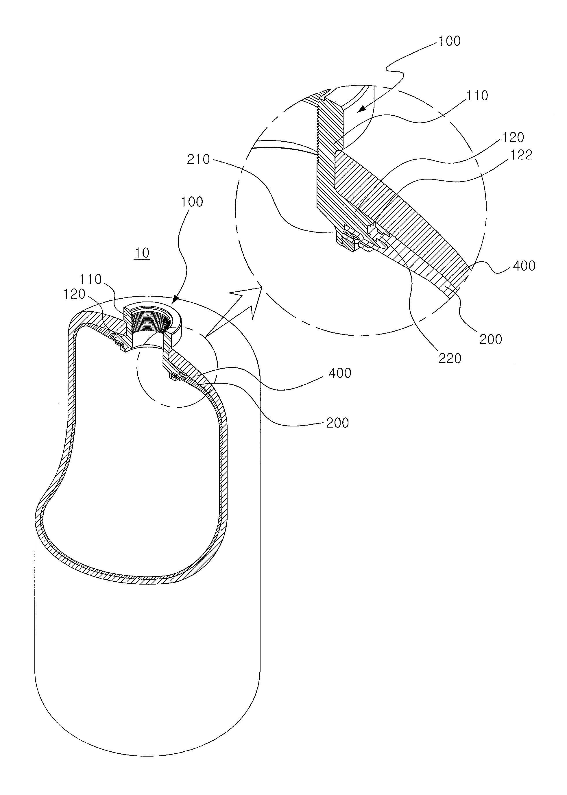
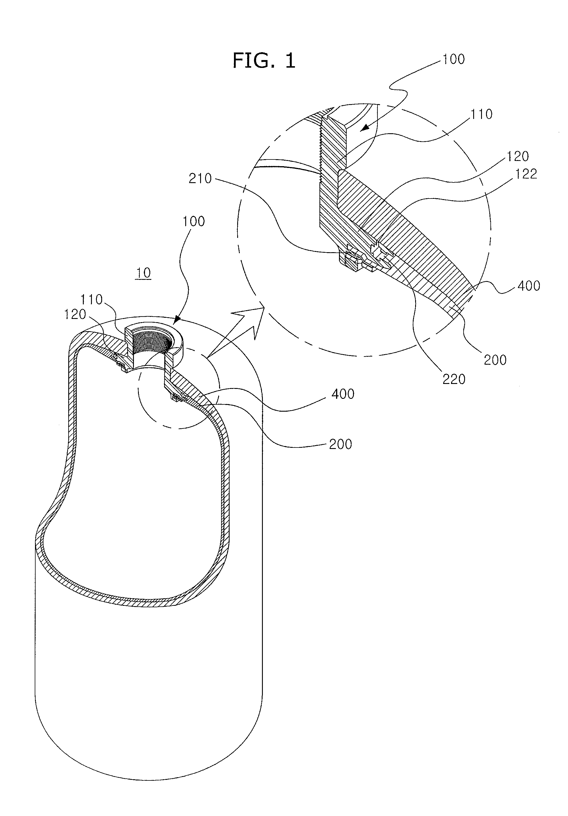
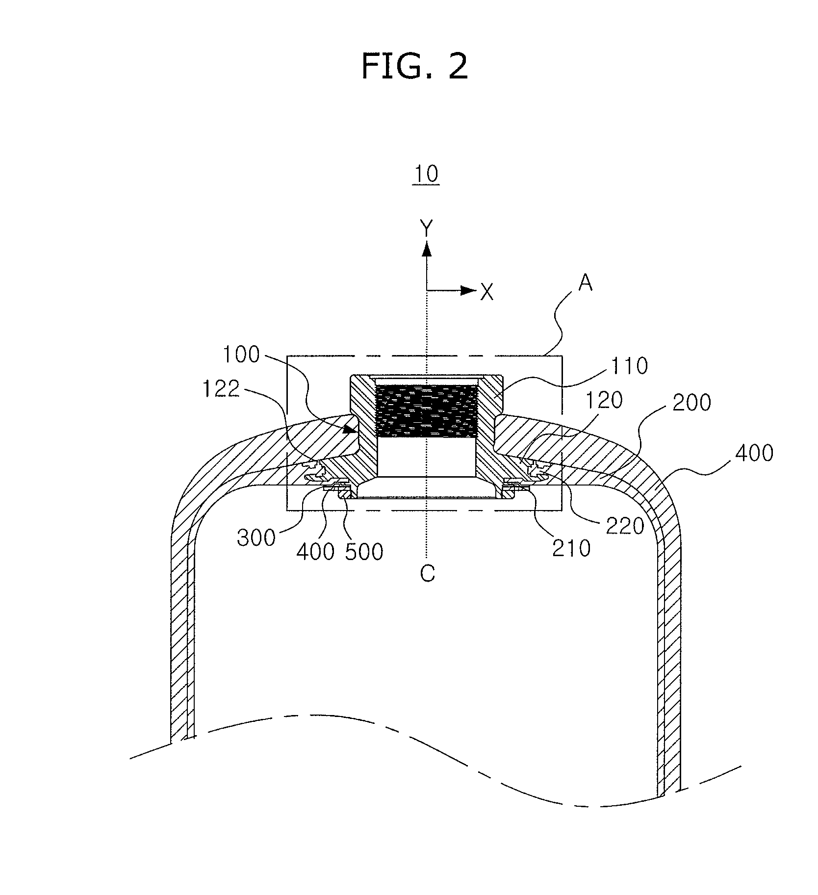
[0050]FIG. 1 is a partial exploded perspective view illustrating a pressure vessel 10 according to an embodiment of the present invention, FIG. 2 is a partial cross-sectional view illustrating the pressure vessel 10, and FIG. 3 is a schematic enlarged view illustrating A of FIG. 2.

[0051]Also, FIG. 4 is a schematic enlarged view illustrating B of FIG. 3, FIG. 5 is a s...


PUM

PropertyMeasurementUnit
Forceaaaaaaaaaa
Pressureaaaaaaaaaa
Sizeaaaaaaaaaa

Abstract

There is provided a pressure vessel. The pressure vessel may include a nozzle-boss comprising a neck part including a hollow portion and a flange part extended outward from the neck part, a liner coupled with the nozzle-boss to provide a space filled with a fluid therein, and a sealing part inserted into a lower end of the neck part to prevent a spillage of the fluid via a boundary between the nozzle-boss and the liner by preventing a direct contact between the fluid and the boundary.

Description

CROSS-REFERENCE TO RELATED PATENT APPLICATION[0001]This application claims the benefit of Korean Patent Application Nos. 10-2012-0133354 filed on Nov. 23, 2012 and 10-2012-0133355 filed on Nov. 23, 2012 in the Korean Intellectual Property Office, the disclosure of which is incorporated herein in its entirety by reference.BACKGROUND OF THE INVENTION[0002]1. Field of the Invention[0003]The present invention relates to a pressure vessel, and more particularly, to a pressure vessel capable of preventing an abnormal leakage of a fluid by preventing a separation between a nozzle-boss and a liner.[0004]2. Description of the Related Art[0005]Pressure vessels are used for storing various fluids such as oxygen, natural gas, nitrogen, hydrogen, etc and are typically manufactured by manufacturing nozzle-bosses and liners by using metallic materials and surrounding nozzle-bosses and liners by carbon fibers or glass fibers or depositing carbon fibers or glass fibers thereon.[0006]However, general...

Claims


Application Information

Patent Timeline
IPC IPC(8): B65D53/06F17C13/00
CPCF17C1/06F17C1/16F17C2201/0109F17C2201/056F17C2203/0604F17C2203/0619F17C2203/066F17C2203/0663F17C2221/011F17C2221/012F17C2221/014F17C2221/033F17C2223/0123F17C2223/035F17C2223/036F17C2260/036F17C2205/0305Y02E60/32F17C13/002
Inventor HEO, SEOK BONGKIM, DO-YEONJEON, SANG JINKIM, SUNG CHULCHOI, BONG WON
Owner ILJIN COMPOSITES CO LTD
Learn More