
Silk-based piezoelectric materials

a piezoelectric material and piezoelectric technology, applied in the field of silk-based piezoelectric materials, can solve the problems of not being able to achieve the desired level of silk piezoelectricity for various applications, not having any insight into the mechanisms and structural changes, and not having provided further studies to achieve the effect of controlling silk piezoelectricity at a desired level for various applications, and ensuring the stability and robust oscillation

Active Publication Date: 2014-05-29
TUFTS UNIV
View PDF0 Cites 24 Cited by
  • Summary
  • Abstract
  • Description
  • Claims
  • Application Information

AI Technical Summary

Benefits of technology

This patent describes the discovery that silk materials can have piezoelectric behavior, similar to quartz. Silk can generate electric charge when mechanical stress is applied, and this property makes it useful in a variety of applications. The patent also describes a process for creating a piezoelectric material from silk by heating and elongating the silk. This process can increase the amount of silk crystals and their alignment, resulting in a more efficient material for energy conversion.

Problems solved by technology

Conventional piezoelectric materials such as certain ceramics or synthetic polymers such as polyvinylidene fluoride may not be suitable for biomedical and biotechnological application due to lack of biocompatibility and biodegradability.
Moreover, there has not been any insight into the mechanisms and structural changes that may be associated with the phenomena observed with silk materials.
More importantly, no further studies have been provided to control silk piezoelectricity at a desired level for various applications.

Method used


Image

  • Silk-based piezoelectric materials
  • Silk-based piezoelectric materials
  • Silk-based piezoelectric materials

Examples


example 1

Materials and Methods

1A. Preparation of Aqueous Silk Fibroin Solutions and Silk Films

[0130]Silk fibroin aqueous solutions were prepared as previously described. See Nazarov et al., 2004. Briefly, Bombyx mori cocoons were cleaned and cut into small pieces. In a subsequent degumming process, sericin, a water-soluble glycoprotein bound to raw silk fibroin filaments, was removed from the silk strands by boiling Bombyx mori cocoons in an aqueous solution of 0.02 M sodium carbonate for 30 minutes to 60 minutes. Thereafter, the remaining silk fibroin bundle was rinsed thoroughly in deionized (DI) water (ρ=18.2 MΩ) to extract the glue-like sericin proteins and allowed to dry overnight. The dried silk fibroin was dissolved in an aqueous solution containing 9.3 M LiBr at room temperature or heated at 60° C. for 4 hours. The silk fibroin solution was dialyzed against DI water using Slide-A-Lyzer® 3.5K MWCO dialysis cassettes (Fisher Scientific, Pittsburgh, Pa.) for 2 days to remove the residua...

example 2

Results and Discussion

2A. Film Processing

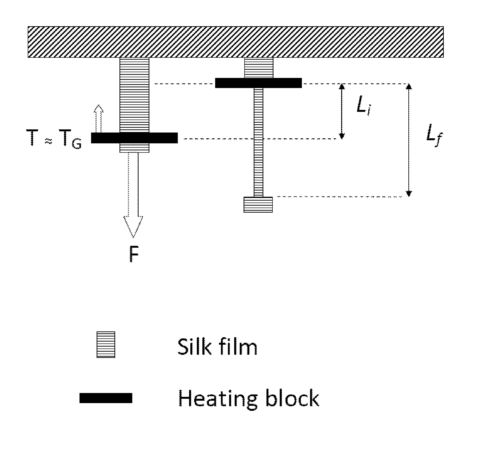
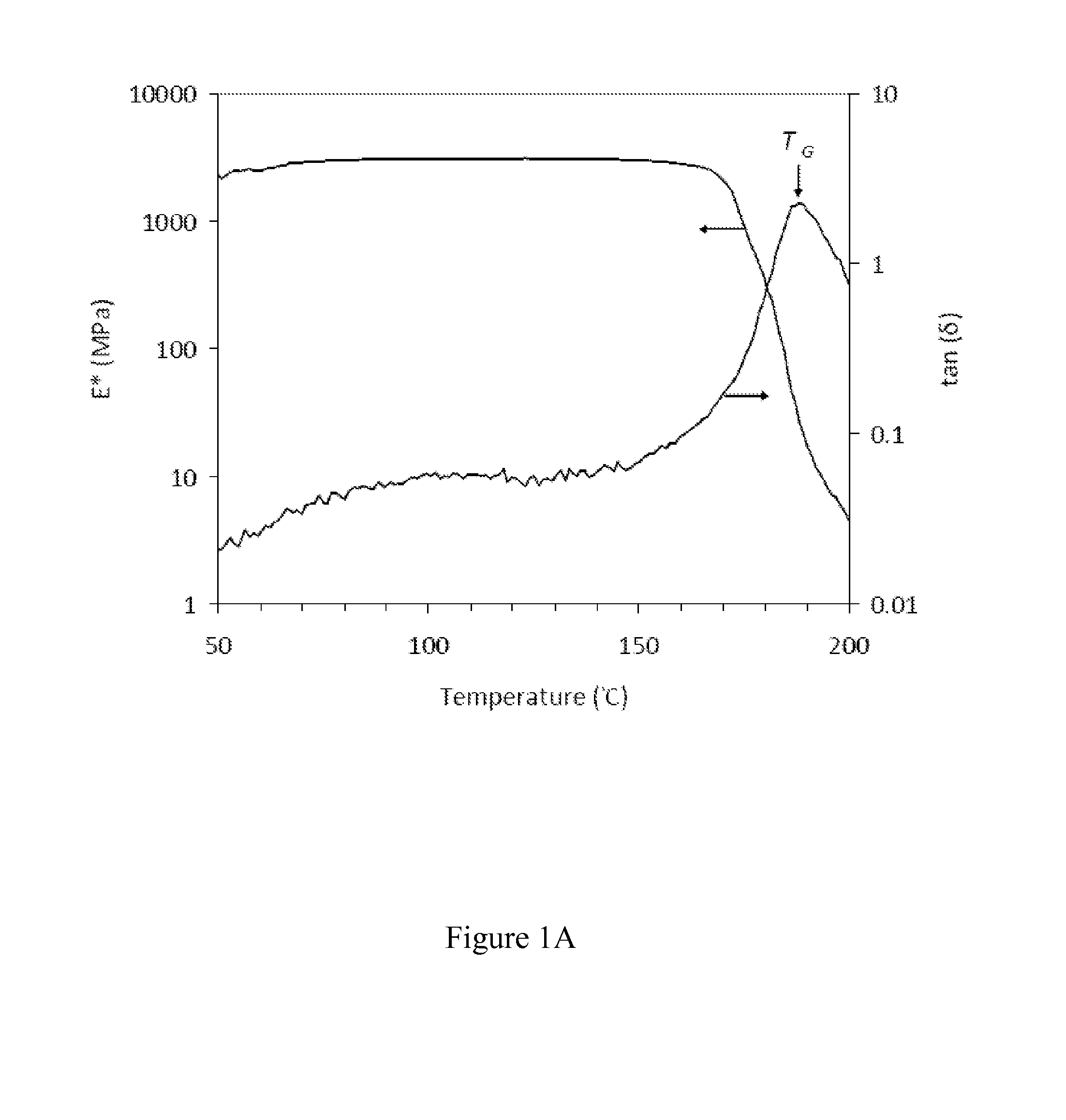
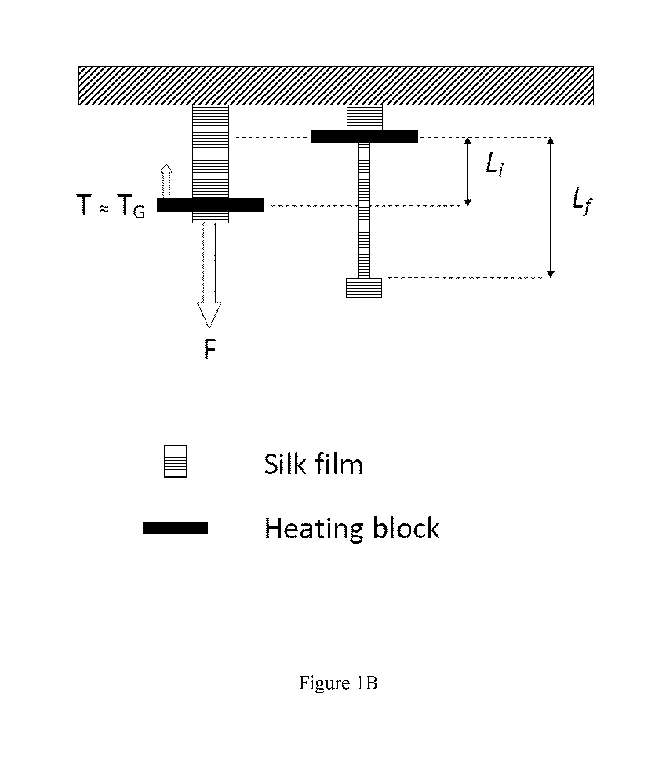
[0139]Dynamic mechanical analysis was employed to establish a suitable temperature for zone-drawing silk fibroin films. FIG. 1A shows typical results of temperature sweeps of the complex dynamic tensile modulus, E*=E*+iE″ (where E is the storage modulus and E″ is the loss modulus) and the loss tangent, tan (δ)=E″ / E′ for silk fibroin films. At a heating rate of 5° C. / min, for temperature ranging from room temperature up to approximately 170° C., E* was essentially constant upon the temperature change and was frequency independent (see, e.g., FIG. 8A); for T>170° C., there was a sharp decrease in E* values that indicated an onset of a “glass transition”. At this heating rate, tan (δ) peaked at 190° C., suggesting a “glass transition temperature” or TG (FIG. 1A). Typically, silk films can be stiff for zone drawing at temperatures lower than TG; whereas drawing silk films at temperatures much higher than TG may render the film brittle and easy to...


PUM

PropertyMeasurementUnit
frequencyaaaaaaaaaa
frequenciesaaaaaaaaaa

Abstract

The invention relates to methods and compositions for preparing silk-based piezoelectric materials and methods for increasing piezoelectricity in silk matrices.

Description

RELATED APPLICATIONS[0001]This International application claims the benefit of and priority to U.S. Provisional Application 61 / 386,592, entitled “Piezoelectric Silk-Based Materials for Biomedical Applications” which was filed Sep. 27, 2010, and 61 / 439,576, entitled “Piezoelectric Silk-Based Materials for Biomedical Applications” which was filed Feb. 4, 2011, the entire contents of which are incorporated herein by reference.GOVERNMENT SUPPORT[0002]The subject matter disclosed herein was made with government support under FA9550-07-1-0079 awarded by the U.S. Air Force and EB002520 awarded by the National Institutes of Health. The U.S. government has certain rights in the invention.BACKGROUND OF THE INVENTION[0003]Piezoelectricity is the ability of certain materials (e.g., crystals, certain ceramics, and biological matter such as bone, DNA and various proteins) to convert mechanical energy into electrical energy or vice versa. Piezoelectric materials can be useful in numerous areas of ...

Claims


Application Information

Patent Timeline
Patent Type & Authority Applications(United States)
IPC IPC(8): H01L41/193H01L21/02H10N30/857H10N30/098H10N30/20H10N30/30H10N30/85
CPCA61N1/36578A61N1/3785H02N2/18H10N30/302H10N30/857H10N30/098H01L21/02
Inventor OMENETTO, FIORENZOKAPLAN, DAVIDYUCEL, TUNA
Owner TUFTS UNIV
Learn More