Lithium ion capacitors and methods of production
a technology lithium ion batteries, applied in the field of lithium ion capacitors, can solve the problems of high cost of cell manufacturing, high cost of cell components, and low energy density of many ultracapacitors for selected purposes
- Summary
- Abstract
- Description
- Claims
- Application Information
AI Technical Summary
Benefits of technology
Problems solved by technology
Method used
Image
Examples
example 1
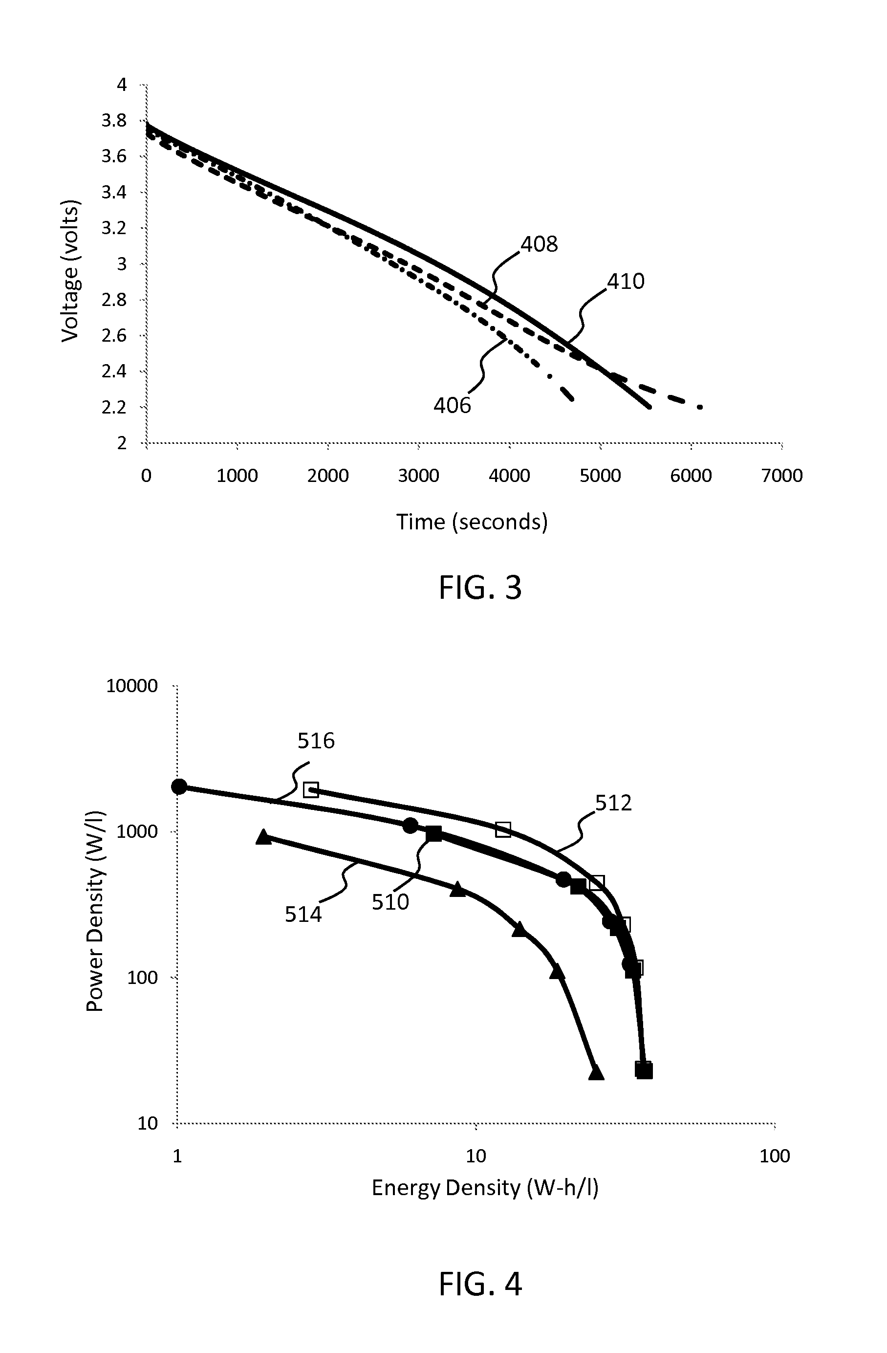
[0054]Lithium-ion button cell capacitors were prepared with various ratios of lithium metal to graphite (anode material) in Samples 1-4.
[0055]To form the anode, a graphite slurry was prepared by mixing 100 g graphite powder (Aldrich), 2 g carbon black (Cabot Corporation), 10 g polyvinylidene fluoride (PVDF) (Alfa Aesar) and 190 g N-methyl-2-pyrrolidone (NMP) solvent (Sigma-Aldrich) to form a smooth slurry. The slurry was dispersed to a thickness of about 1 mm onto copper foil using a doctor-blade. The graphite slurry-coated copper foil was initially dried in a fume hood, vacuum dried in a 120° C. oven, and then diced into 1.4 cm diameter electrodes. The typical thickness of the graphite electrodes (graphite plus copper current collector) was about 17 mm.
[0056]To form the cathode, activated carbon films were made by grinding activated carbon powder and PTFE binder at a ratio of 90:10 by weight at a speed of 350 rpm to form a mixture that was rolled into a thin sheet. A typical thickn...
example 2
[0066]Lithium-ion button cell capacitors were prepared using hard carbon as the anode material.
[0067]Sample 5. Ground phenolic resin was heated to 660° C. at a heating rate of 200° C. / hour, held at 660° C. for 2 hours to carbonize the resin, and then cooled to room temperature. The thermal cycle was performed under N2 atmosphere with a gas flow rate of 6.18 l / min. The resulting carbon was soaked in 37% HCl overnight and rinsed with deionized water to remove trace impurities. The sample was further soaked in a 29% NH4OH aqueous solution overnight, followed by rinsing with deionized water. Carbon slurry was prepared using 100 g of the resulting carbon, 10 g polyvinylidene fluoride (PVDF), 2 g carbon black and 190 g NMP solvent.
[0068]The lithium-ion capacitor of Sample 5 included 35 mg activated carbon (cathode), 48 mg of the above-described hard carbon (anode), and 13.2 mg lithium composite particles comprising 20% LiPF6.
[0069]Sample 6. Ground phenolic resin was heated to 1000° C. at ...
example 3
[0081]Lithium metal particles in silicone oil were first washed and filtered with THF under controlled atmosphere to remove the silicone oil. The particles were dried and transferred to a dish containing a 2M coating solution of LiPF6 dissolved in THF. The solvent evaporates under ambient conditions to produce stabilized, LiPF6-coated lithium composite particles. The amount and concentration of the coating solution was controlled to produce composite particles where, upon drying, the weight ratio of LiPF6 (coating) to lithium metal (core) is about 20:80.
[0082]SEM micrographs of the coated particles are shown at high and low magnifications respectively in FIGS. 7A and 7B. Micrographs of the uncoated particles are not available due to their highly pyrophoric nature. In a 1 week evaluation, the coated particles remained stable at room temperature in air. In a further evaluation, the coated particles exhibited no reaction following overnight exposure in an oven at 150° C.
PUM
 Abstract
Description
Claims
Application Information
 - R&D
- Intellectual Property
- Life Sciences
- Materials
- Tech Scout
- Unparalleled Data Quality
- Higher Quality Content
- 60% Fewer Hallucinations
Browse by: Latest US Patents, China's latest patents, Technical Efficacy Thesaurus, Application Domain, Technology Topic, Popular Technical Reports.
© 2025 PatSnap. All rights reserved.Legal|Privacy policy|Modern Slavery Act Transparency Statement|Sitemap|About US| Contact US: help@patsnap.com


