Limb Protection Device

a technology for protecting devices and limbs, applied in non-surgical orthopedic devices, medical science, diagnostics, etc., can solve problems such as low limbs, risk of injury, and limb's constituent structures, and achieve the effect of limiting overheating of joints

Active Publication Date: 2014-05-29
HORSEPOWER TECHNOLOGIES INC
View PDF2 Cites 14 Cited by
  • Summary
  • Abstract
  • Description
  • Claims
  • Application Information

AI Technical Summary

Benefits of technology

[0070]Furthermore, it is important that these be accomplished without adversely affecting the horse's proprioceptive ability, while

Problems solved by technology

The horse's large body size, slender limb structure and occasional need for high speed or rapid acceleration expose the lower limbs, in particular, to risk of injury, either from a single traumatic event such as blunt force trauma or a mis-step of the hoof, or from accumulated micro-damage sustained, for example, during repeated loading of the limb during race training.
Injury arising from a single incident can affect any of the limb's constituent structures, although the more distal (lower limb) components are generally at greater risk by virtue of their proximity to the ground and ground obstructions.
In particular, the fetlock joint, at which the cannon bone meets the pastern bone, is extremely vulnerable to injury, often with catastrophic results.
This higher load may lead to injury, especially if it occurs repetitively.
Once sustained, injury—be it to bone or soft tissue—requires substantial periods of complete rest or much reduced exercise before the animal can return to normal activity, and in some cases the recovery is never complete.
Man's competitive use of horses—which frequently exceeds ‘normal activity’—places additional and frequently unreasonable demands on the healing tissues.
As a result, the healing process can be exacerbated and the injury will fail to fully resolve, causing a chronic and sometimes life-long limitation of use.
Additionally, while bone is unusual in being able to completely heal itself, soft tissues generally heal with some degree of scar formation which results in added compromise of ambulatory ability, mediated, for example, by pain or adhesions.
Scar tissue (unspecialized fibrous tissue in an orientation that is mechanically inferior and/or predisposed to forming adhesions to adjacent structures) is also invariably less strong than undamaged tissue, placing the injured tissue(s) at risk of re-injury.
The situation is complicated by an incomplete understanding of lower limb mechanics, sometimes resulting in contradictory data findings or theorems.
As will be apparent, most of the prior art devices shown in the patents and applications mentioned above are simply intended to protect the horse's legs from direct impact damage,

Method used


Image

  • Limb Protection Device
  • Limb Protection Device
  • Limb Protection Device

Examples


first embodiment

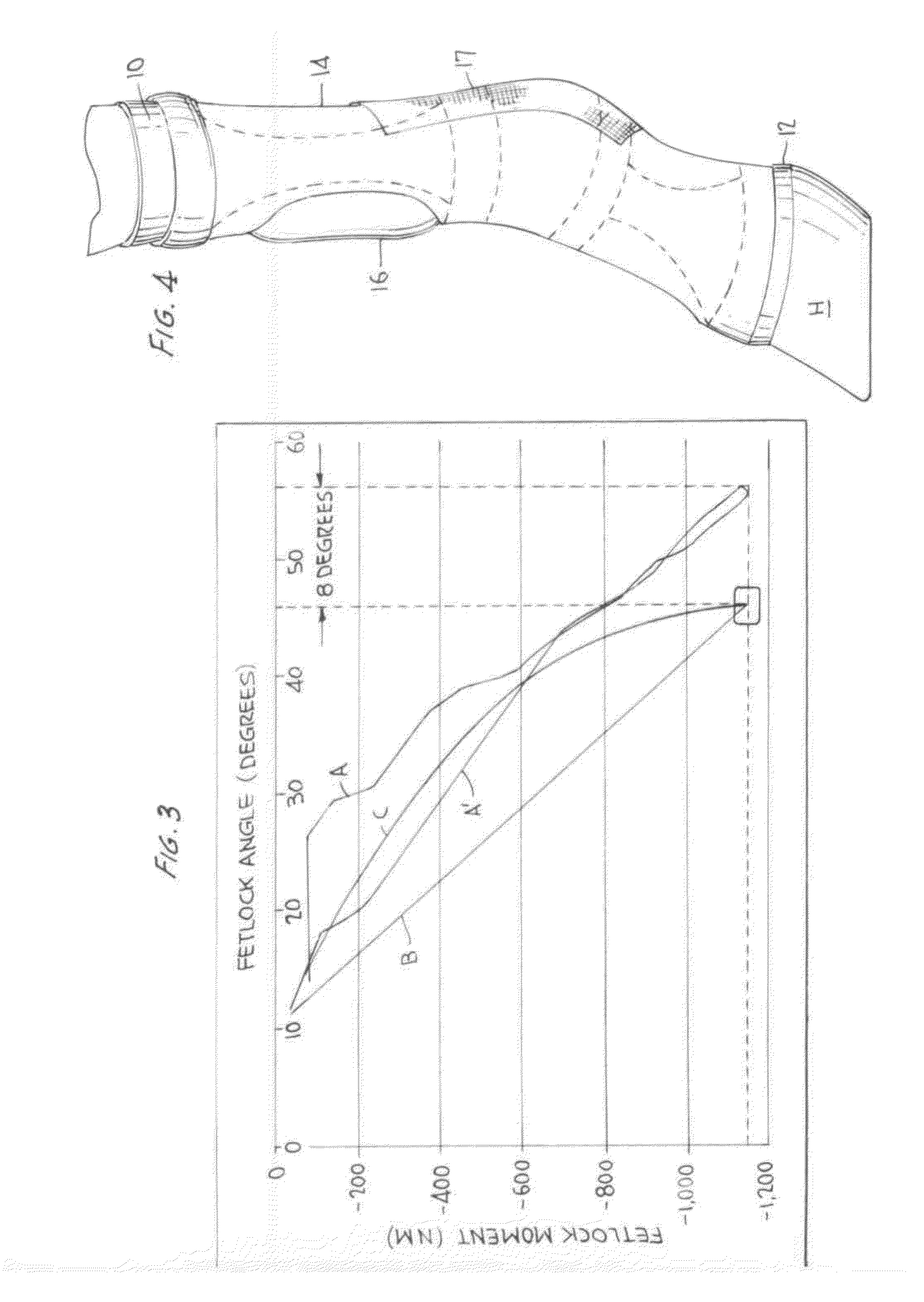
[0114]Another goal of the present invention is to protect the fetlock region from impact damage, to provide cooling and moisture wicking insofar as possible, to damp vibration, and to provide abrasion resistance to the fetlock. FIG. 4 shows the outer structure of the device according to the invention, which provides these features. The structural elements that are directed to the other objects of the invention mentioned above are disposed within the outer structure of FIG. 4, or between inner and outer sleeves thereof, and are discussed more fully below.

[0115]Thus, as illustrated in FIG. 4, the device of the invention comprises an inner sleeve 10 made of a moisture-wicking breathable material (such as that known as Coolmax, or possibly that known as X-static) extending the length of the device, which is shown in use, that is, installed over a horse's fetlock. The lower end of inner sleeve 10 is terminated by an elastomeric seal 12, sealing sleeve 10 to the upper portion of the horse...

second embodiment

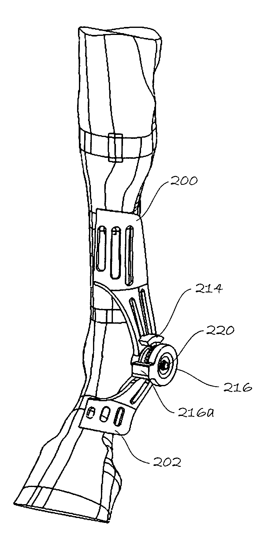
[0138]As mentioned above, FIGS. 17-20 show the device of the invention, while FIG. 21 shows a detail of a tensile member used to provide additional energy storage, reducing the loads on the tendons and associated structures of the joint, as described above in connection with FIG. 2.

[0139]In this embodiment, the device 100 is shown in the left-side view of FIG. 17 over an equine fetlock, shown in phantom; in FIG. 18, from the front; in FIG. 19, from the rear, and in FIG. 20, in a perspective view from the left side as in FIG. 17, but with outer structure removed to illustrate the underlying structure.

[0140]As shown, device 100 includes two upper cuffs 102 and 104, disposed above the fetlock, and secured thereto by straps 110, 112, 114, and one saddle member 106 secured below the fetlock by a strap 116. Cuffs 102 and 104, and saddle member 106 may be molded of tough plastic material and provided with suitable interior padding, e.g., of the Sorbothane material mentioned above. Upper cu...

fourth embodiment

[0145]FIGS. 31-38 show several variations on the joint protective device of the invention, wherein a different structure is employed to add support for the tendons of the joint. Again, these embodiments are shown in connection with the fetlock of a horse, but could be adapted to other joints of other animals, including humans. FIGS. 31 and 32 show an embodiment wherein support for the joint only is provided, while FIGS. 33-36 add structure for limiting the range of motion (ROM) of the joint, particularly useful during rehabilitation after injury or surgery. Finally, FIG. 37 shows an alternative wherein range of motion limitation only is provided. FIG. 38 shows a preferred padding structure.

[0146]In each of FIGS. 31-35 and 37, the device of the invention is shown in part; that is, only one side of the device is shown. Further, FIGS. 31-34 and 37 show the device on the leg of a horse, while FIG. 35 shows the device half alone. It will be understood that the complete device will includ...


PUM


Abstract

A joint-supporting device comprises tensile members extending from a proximal cuff secured to the limb above the joint to a distal cuff secured to the limb below the joint, supplementing the tensile characteristics of the joint's tendons, ligaments, and other structure. The device may also comprise structure for limiting the range of motion and angular velocity of the joint.

Description

FIELD OF THE INVENTION[0001]The invention herein relates to a device to prevent damage to body joints, in particular to prevent injury to both hard and soft tissues, e.g., during athletic activity, and also for support during rehabilitation from injury or surgery. The invention is described in several embodiments optimized for prevention of equine lower limb injuries and for rehabilitation thereof, but is not limited thereto.[0002]More specifically, the invention is disclosed in a first embodiment, represented by FIGS. 5-13A and 16, in which the joint protective device comprises proximal and distal structures secured to the limb on either side of the joint to be protected. Tensile members which are not resilient extend from the proximal structure to the distal structure to support the joint and limit its range of motion. Dilatant materials may be provided to limit the angular velocity of the joint. The proximal and distal structures are not joined to one another, such that in order ...

Claims


Application Information

Patent Timeline
IPC IPC(8): A61F5/01A61D99/00
CPCA61F5/0102A01K13/007A61B5/1071A61B5/1121A61B2503/40A61D9/00A61D99/00A61F5/0111A61F2005/0167A61F2005/0172A61F2005/0179
Inventor PFLASTER, DANIEL SCOTTCRISCO, JOSEPH J.FIORE, RUSSELL D.DRUMM, WENDYMILLER, RICHARD L.KIRKER-HEAD, CARL A.SIZE, KRISTIN JUGENHEIMERTORRISI, GREGORY SCOTTSWAI, PETERLINNANE, JENNIFERMORSE, CHRISTOPHER JOHN
Owner HORSEPOWER TECHNOLOGIES INC
Why Eureka
Try Eureka