Structure to reduce noise and vibration in an engine system

a technology of engine system and structure, which is applied in the direction of machines/engines, combustion air/fuel air treatment, mechanical equipment, etc., can solve the problems of increasing the weight of the surface sound radiation, the noise of the surface sound may be considered undesirable, and the airflow through the system may develop chaotic features, etc., to reduce the turbulent noise, increase the structural rigidity of the manifold assembly, and the effect of reducing the nois

Inactive Publication Date: 2014-06-19
FORD GLOBAL TECH LLC
View PDF6 Cites 4 Cited by
  • Summary
  • Abstract
  • Description
  • Claims
  • Application Information

AI Technical Summary

Benefits of technology

[0003]Some approaches aimed at reducing turbulent noise in the engine manifold system involve increasing the structural rigidity of the manifold assembly by adding ribs to the outside of the manifold. Added ribbing stiffens the structure and thereby reduces vibrations in the engine system. US 2010/0326395 A1 shows an example system having ribs and braces added to the outside surface of an intake manifold cover in order to stiffen the assembly and reduce noise from vibrations within the system. An alternative approach to reducing vibrations within a system, and therefore the noise transmitted, involves adding a thin layer of absorbent material to the walls of an engine component. In US 2006/0201470 A1, a system is described wherein two walls of an engine component, e.g. an engine cover or manifold wall, is reinforced with a honeycomb layer of absorbent padding. In the three-layer system described, wherein the absorbent honeycomb layer is sandwiched between two walls, the middle layer also contains a substantial amount of air and so acts as a noise insulator to reduce vibrations and the noise transmitted.
[0004]The inventors herein have recognized the above issues, as well as limitations related to such approaches. For example, addition of structural ribs to an engine component, for instance, an intake manifold, may also increase its weight, manufacturing cost, and overall size due to the traversal of the ribs spanning various surfaces. F

Problems solved by technology

Since the tubular shapes of air induction systems may be complex, the flow of air through the system may develop chaotic features that affect how the fluid interacts with the surface of the tube through which it flows.
Sound radiated from the surface may be considered undesirable noise.
For example, addition of structural ribs to an engine compone

Method used


Image

  • Structure to reduce noise and vibration in an engine system
  • Structure to reduce noise and vibration in an engine system
  • Structure to reduce noise and vibration in an engine system

Examples


Embodiment Construction

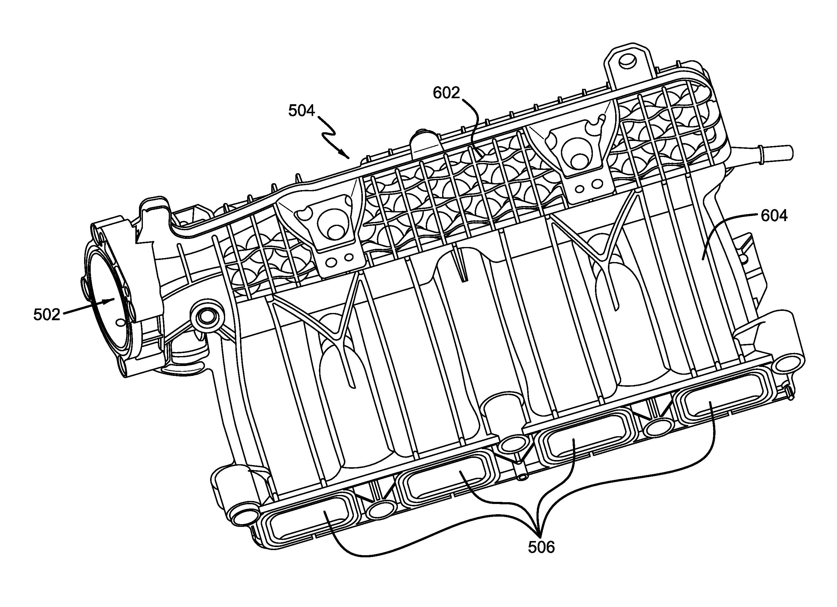
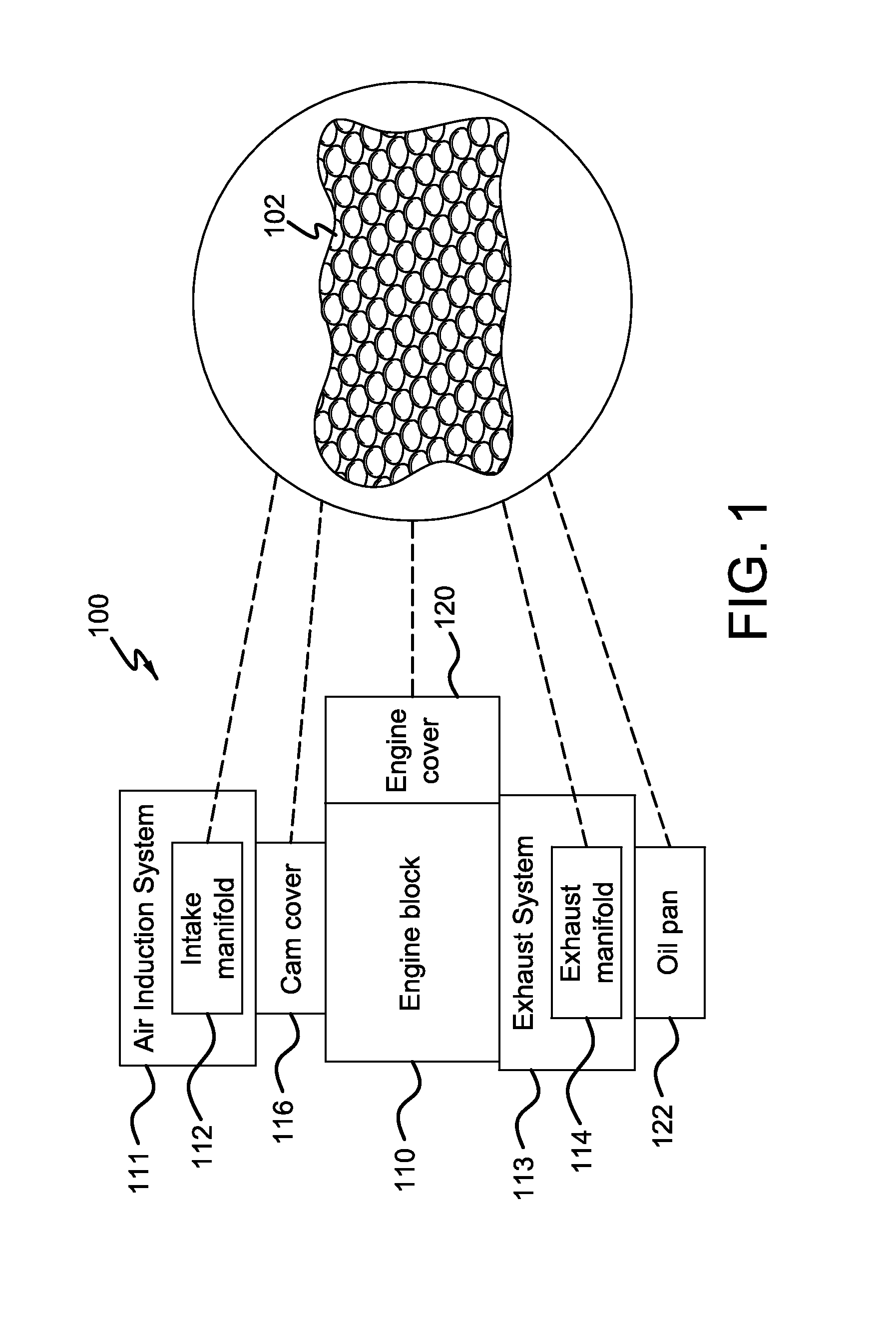
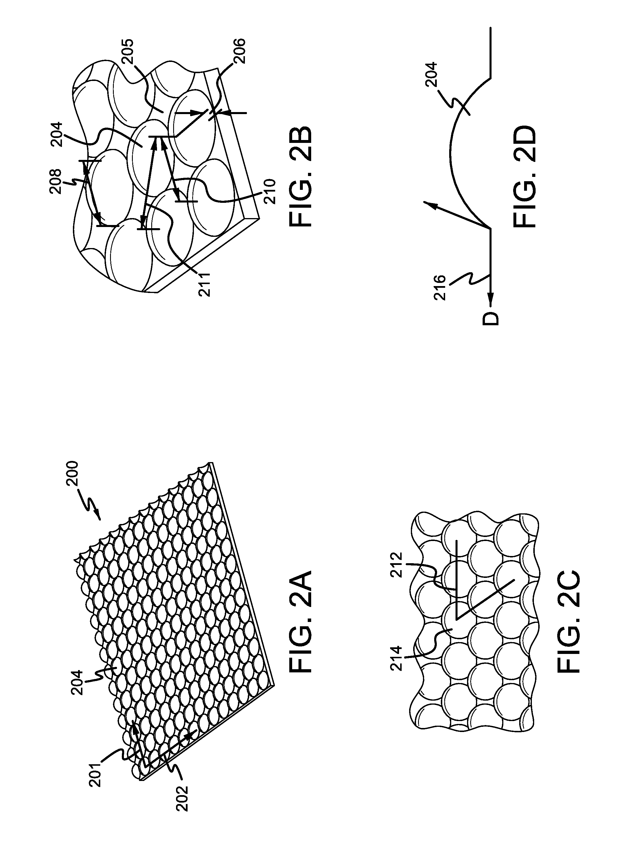
[0019]Methods are described for reducing noise radiated in an engine system. In one example, polydome protuberances on planar surfaces of an intake manifold are positioned in a grid-like manner to increase the structural rigidity of the surface and thereby reduce the noise radiated due to vibrations on the surface. However, other engine components and devices may take advantage of such protuberances, such as a cam cover, a front cover, etc. In this regard, FIG. 1 presents a schematic diagram showing example engine components having planar surfaces wherein the described polydome protuberances may be applicable. FIGS. 2-4 show example surfaces with dome-shaped protuberances whose dimensions and spatial arrangements are adjusted to reduce noise in various frequency ranges. The polydomal features offer various advantages, including improving overall packaging space, wall thickness, weight, time-to-freeze, etc. FIGS. 5-12 shows an exemplary intake manifold including example polydome prot...


PUM

PropertyMeasurementUnit
Weightaaaaaaaaaa
Thicknessaaaaaaaaaa
Diameteraaaaaaaaaa

Abstract

Adding dome-shaped protuberances, or polydomes, to an engine system increases the structural integrity of the engine component to which they are added and allows noise radiated in the engine system to be reduced in certain regions of the frequency spectrum without incurring a significant increase in the mass of the engine part to which they are added, which may result in a longer solidification time during the mold injection process. The size and spatial arrangement of polydomes relative to one another can be further adjusted to reduce noise within the engine system and polydomes may be reinforced with ribs to increase the structural stiffness of plastic engine components. Because plastic engine components are created using an injection mold process during the manufacturing process, added surface features (e.g. polydomes and ribs) are continuous with the underlying planar surface to which they are added.

Description

FIELD[0001]The present description relates to reducing the noise in an internal combustion engine.BACKGROUND AND SUMMARY[0002]Internal combustion engines have an air intake system that directs ambient air to the combustion cylinders. Since the tubular shapes of air induction systems may be complex, the flow of air through the system may develop chaotic features that affect how the fluid interacts with the surface of the tube through which it flows. For instance, airflow through a composite intake manifold may develop pressure fluctuations within the cavity and introduce turbulent features into the airflow pattern in a manner that depends on the shape of the cavity. The turbulence induced may then affect how the air transfers its energy to the surface and in response, vibrations may develop in the walls that produce sound radiations in certain regions of the frequency spectrum. The vibrational modes and sound frequencies may further depend on the geometric arrangement of the tube and...

Claims


Application Information

Patent Timeline
IPC IPC(8): F02B77/00
CPCF02B77/00F02M35/10321F01N13/10F01N2260/20F02B77/13F02M35/10347F02M35/112F02M35/1277
Inventor MOETAKEF, MOHAMMAD ALIKILBY, JOHN G.PETERS, EDWARD WILLIAMKOSKO, JEFF RICHARDSIDDIQUI, ABDUL SAMI
Owner FORD GLOBAL TECH LLC
Why Eureka
Try Eureka