Closure of Cooling Holes with a Filing Agent

a filing agent and cooling hole technology, applied in the field of gas turbine engines, can solve the problems of increasing the cooling air flow on the component, affecting the performance of the gas turbine engine, and often needing to remove old tbc, etc., and achieve the effect of not deteriorating the gas turbine engin

Active Publication Date: 2014-06-19
RTX CORP
View PDF5 Cites 22 Cited by
  • Summary
  • Abstract
  • Description
  • Claims
  • Application Information

AI Technical Summary

Benefits of technology

[0015]In another refinement, the step of curing the filling agent to block the plurality of first cooling holes may prevent cooling fluid to pass through the plurality of first cooling holes.
[0024]In another refinement, the filling agent may comprise a metal alloy powder to provide surface uniformity between the first cooling holes and the surrounding surface of the component.
[0028]In another refinement, the filling agent may be capable of withstanding a temperature of more than 550° C. without deterioration of the gas turbine engine.

Problems solved by technology

When a TBC is damaged during operation or when a new design of TBC needs to be installed, the old TBC often needs to be removed before the new TBC is applied.
However, the presence of open cooling holes on the exposed surface of the engine component poses a significant problem for the successful application of a new, high quality TBC layer.
Specifically, a non-uniform (or uncompacted) TBC surface susceptible to spallation frequently results when a new TBC layer is directly applied over pre-existing open cooling holes remaining after removal of the old TBC layer.
In particular, since new cooling holes are drilled to meter a specific quantity of cooling air on the engine component after a new TBC layer is applied, any subsequent coating spallation may lead to opening of the pre-existing holes and cause an increase in cooling air flow on the component, as cooling air flow is metered by the size and quantity of the cooling holes.
The increase in cooling air flow on the component may subsequently starve other downstream components of cooling air causing the downstream components to suffer from structural damage associated with operating at higher than designed temperatures.
One problem with the brazing approach is that a typical braze material will incrementally lower the incipient melting temperature of areas of inhomogeneous chemistry in the metal alloy of the component, especially on castings, due to the diffusion of boron or silicon into the base metal alloy from the braze material.
A second problem with brazing is that wrought alloy properties will be reduced by exposure to brazing process temperatures.
Lower melting brazes could be prone to re-melting and with a possibility of resolidifying elsewhere on alloys adversely affected by exposure to the low melting braze constituents.
Welding attempts of the old set of cooling holes has proven to introduce substantial distortion into the part associated with solidification of the welds.

Method used


Image

  • Closure of Cooling Holes with a Filing Agent
  • Closure of Cooling Holes with a Filing Agent
  • Closure of Cooling Holes with a Filing Agent

Examples


Embodiment Construction

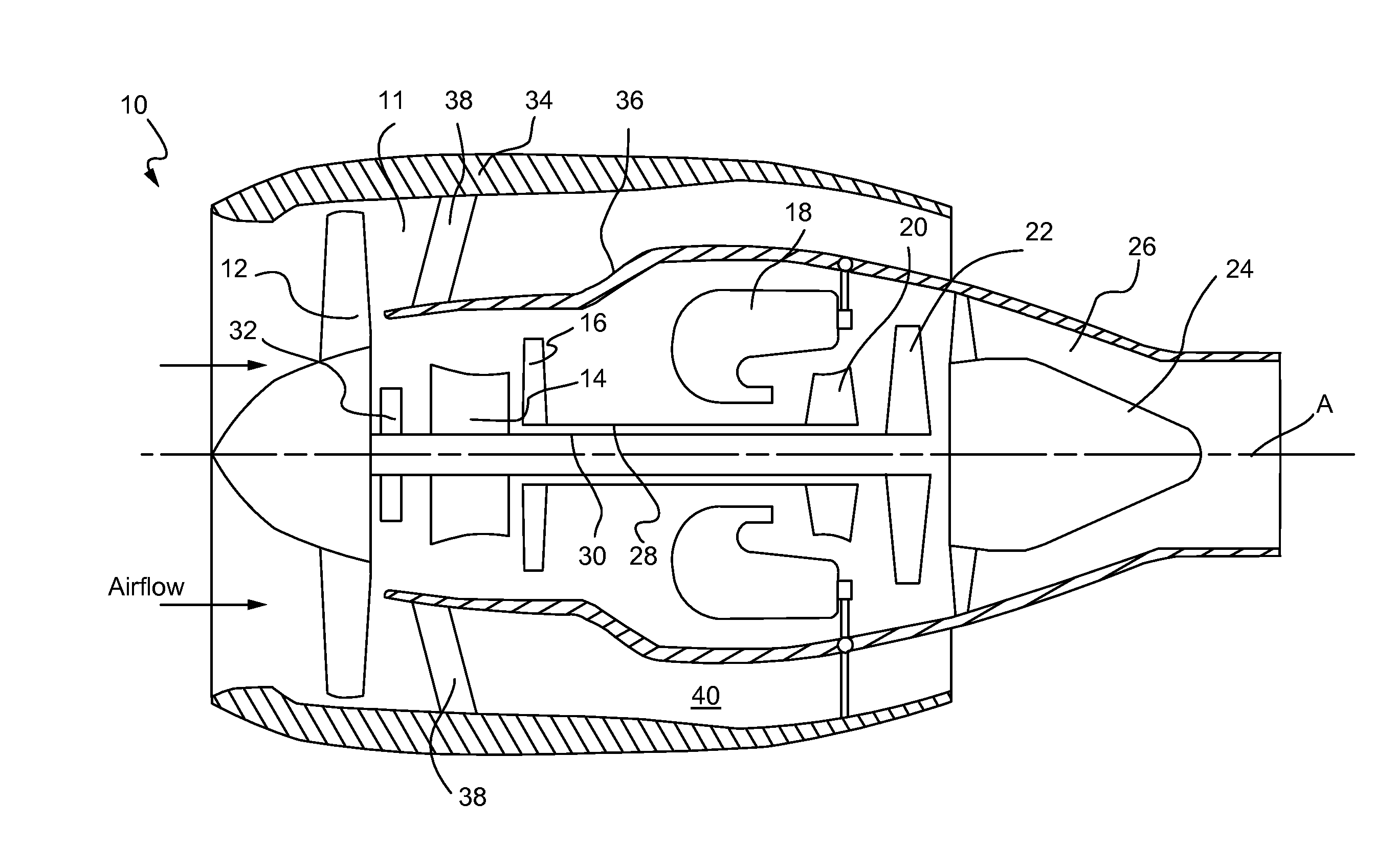
[0040]Referring now to the drawings, and with specific reference to FIG. 1, there is depicted an exemplary gas turbine 10 wherein various embodiments of the present disclosure may be utilized. In this example, the industrial gas turbine 10 may include a compressor section 11 which may comprise, sequentially from the forefront of the gas turbine engine 10, a fan 12, a low pressure compressor 14, a high pressure compressor 16, a combustor chamber 18 downstream of the compressor section 11, a high pressure turbine 20 and a low pressure turbine 22 both downstream of the combustor chamber 18, a tail cone 24, and an exhaust nozzle 26. Further, a high pressure shaft 28 may couple the high pressure compressor 16 with the high pressure turbine 20, while a low pressure shaft 30 may couple the low pressure compressor 14 with the low pressure turbine 22. Both shafts 28 and 30 may be rotatable about an axis A. The low pressure shaft 30 may drive the fan 12 through a gear train 32. On the outside...


PUM

PropertyMeasurementUnit
temperatureaaaaaaaaaa
diameteraaaaaaaaaa
diameteraaaaaaaaaa

Abstract

A method for filling cooling holes in a component of a gas turbine engine is disclosed. The component may include a plurality of first cooling holes penetrating the wall of the component. The method may comprise the steps of exposing the outer surface of the component, filling the plurality of first cooling holes of the component with a filling agent, curing the filling agent to block the passage of air through the cooling holes, and applying a thermal barrier coating over the surface of the component. The method may further include installing a second plurality of cooling holes, the second plurality of cooling holes penetrating the thermal barrier coating and the wall of the component and allow air to pass therethrough.

Description

FIELD OF THE DISCLOSURE [0001]The present disclosure generally relates to a gas turbine engine and, more particularly, relates to the closure of cooling holes of a component within a gas turbine engine.BACKGROUND OF THE DISCLOSURE [0002]A gas turbine engine commonly includes a fan section, a compressor, at least one combustor, and a turbine. The compressor and turbine each include a number of rows of blades attached to a rotating cylinder. In operation, the air is pressurized in a compressor and is then directed toward the combustor. Fuel is continuously injected into the combustor together with the compressed air. The mixture of fuel and air is ignited to create combustion gases that enter the turbine, which is rotatably driven as the high temperature and high pressure combustion gases expand in passing over the blades forming the turbine. Since the turbine is connected to the compressor via a shaft, the combustion gases that drive the turbine also drive the compressor, thereby res...

Claims


Application Information

Patent Timeline
Patent Type & Authority Applications(United States)
IPC IPC(8): F02C7/12
CPCF01D5/288F01D25/12F05D2230/90B23P6/002B23P2700/06F01D5/284Y02T50/60F02C7/12F01D5/18C23C4/00C25D7/04
Inventor BOGUE, WILLIAMPRIHAR, RON I. P. E.
Owner RTX CORP
Why Eureka
Try Eureka