Curved Automatic-Darkening Filter

Inactive Publication Date: 2014-06-19
3M INNOVATIVE PROPERTIES CO
7 Cites 69 Cited by

AI-Extracted Technical Summary

Problems solved by technology

Existing flat-glass automatic darkening filters can, however, add considerable weight to the final product (such as welding shield), which in turn, can create stress and tension in the user's neck and shoulders.
The rectangular configuration of...

Benefits of technology

[0029]The inventive switchable filter is beneficial in that overall product weight can be reduced relative to known commercially-available products. Reductions in weight are achieved by the, low weight of the flexible glass layers. These flexible layers tend to be thinner than the flat glass substrates that have been used in previous conventional products. Further, the inventive sw...

Abstract

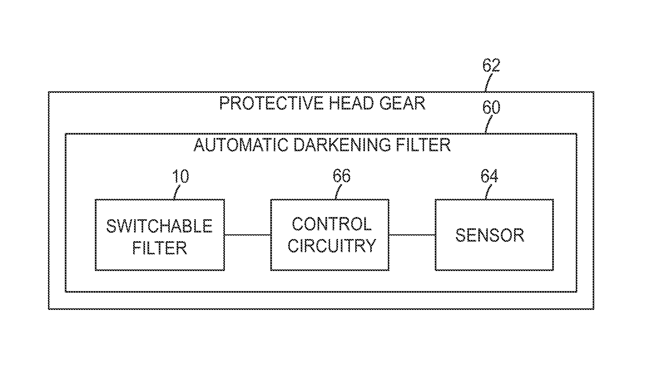
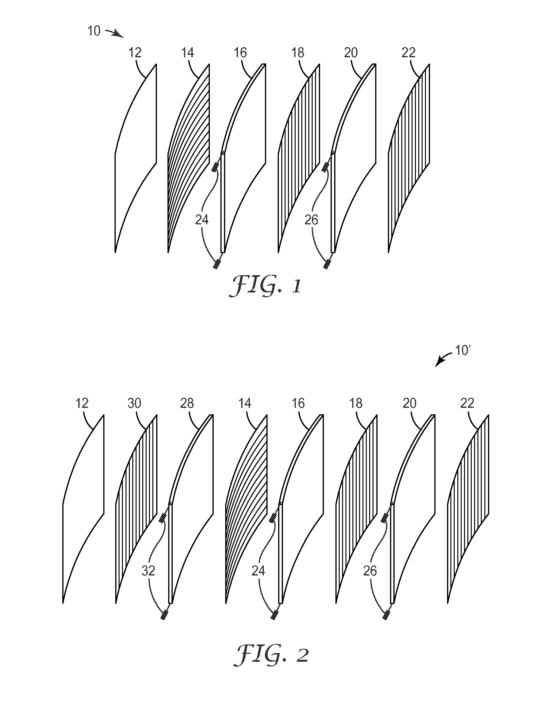
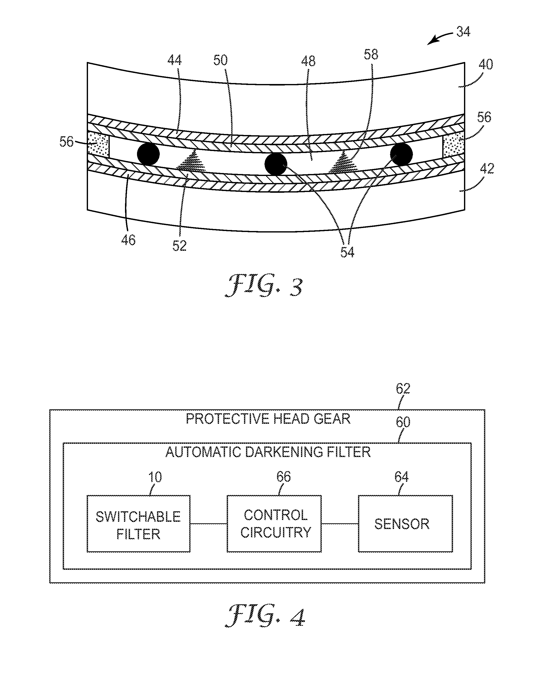
An automatic-darkening filter 10, 10′ that comprises a first polarizer 14, a second polarizer 18, a first liquid-crystal cell 16, and a sensor 64. The first polarizer 14 has a first polarization direction, and the second polarizer 18 has a second polarization direction. The liquid crystal cell 16 is disposed between the first and second polarizers 14, 18 and contains first and second optically-transparent, flexible, glass layers 40 and 42 with the liquid crystal layer 48 being located between these layers. The sensor 64 detects incident light and causes a signal to be sent, which causes molecular rotation within the liquid crystal layer. The inventive automatic-darkening filter is beneficial in that overall product weight can be reduced and the view field can be increased.

Application Domain

Technology Topic

Image

  • Curved Automatic-Darkening Filter
  • Curved Automatic-Darkening Filter
  • Curved Automatic-Darkening Filter

Examples

  • Experimental program(1)

Example

EXAMPLE
Liquid Crystal Cell Assembly
[0047]A curved liquid crystal cell for an automatic welding filter was made in the following manner.
[0048]The starting flexible glass layer was a 0.1 mm thick D263T glass from Schott Glass of Schott Glas Export, GmbH, located at Rheinallee 145, 55120 Mainz, Germany. The glass was sputter deposited with indium tin oxide (ITO). The conductivity of the coated ITO was roughly 100 ohm/square. The ITO glass was coated with a thin layer of polymide polymer. A commercially-available polyimide alignment material was coated onto the glass using a spin coating technique. The dried coating thickness was between 80 nanometers (nm) and 200 nm. The thin polymide layer was aligned by brushing it with using a rotating felt cloth. This brushed polymide, ITO/glass piece was cut into pieces for the top and bottom portion of the liquid crystal cell. A first piece (top) of glass was rotated 90° from the orientation of the second (bottom) piece of glass to provide proper alignment.
[0049]The curved, liquid-crystal cell was formed using a metal cylinder that had a radius of approximately 90 millimeters (mm) as the template. The bottom portion of the cell, the ITO glass having the rubbed polyimide coating, was taped to the metal cylinder using 3M Magic Tape™. An edge adhesive (UV curing Norland 68 optical adhesive) was applied to the bottom portion using a syringe and needle. A twisted, nematic, liquid-crystal mixture was combined with 1% by weight of 4 micrometer (μm) ceramic spacer beads. The liquid crystal/spacer bead mixture was placed on the bottom portion of the cell using a pipette. The top portion of the cell was attached to the bottom portion at the leading edge using 3M Removable Tape™. A polyester film, that was attached to the metal cylinder on one end, was used to wrap and curve the top portion of the cell onto the bottom portion. A rubber roll was used to compress the top portion onto the bottom portion. Tension was maintained on the polyester film to keep the components of the cell in close contact. Using a UV light source for 5 minutes, the UV curing edge adhesive was then cured. The completed cell was then removed from the cylinder by removing the polyester film and pieces of tape. Polarizing films were attached to the bottom and top portions using a pressure-sensitive adhesive. The polarizing films were orthogonal to each other and corresponded to the alignment that was rubbed into the polyimide layer. Copper tape, with conductive adhesive, was attached to the ITO on the top portion, and another piece of copper tape with conductive tape was attached to the ITO on the bottom portion. A 10 volt potential was placed across the cell through the copper tape. The cell switched from a light state to a dark state when the voltage was applied. The dimensions of the finished cell were approximately 75 mm wide and 75 mm long (5625 mm2; 56.25 cm2) with a curvature that was slightly less than the 100 mm radius of the original cylinder.
[0050]This invention may take on various modifications and alterations without departing from its spirit and scope. Accordingly, this invention is not limited to the above-described but is to be controlled by the limitations set forth in the following claims and any equivalents thereof.
[0051]This invention also may be suitably practiced in the absence of any element not specifically disclosed herein.
[0052]All patents and patent applications cited above, including those in the Background section, are incorporated by reference into this document in total. To the extent there is a conflict or discrepancy between the disclosure in such incorporated document and the above specification, the above specification will control.

PUM

PropertyMeasurementUnit
Weight
Flexibility
Transparency
tensileMPa
Particle sizePa
strength10

Description & Claims & Application Information

We can also present the details of the Description, Claims and Application information to help users get a comprehensive understanding of the technical details of the patent, such as background art, summary of invention, brief description of drawings, description of embodiments, and other original content. On the other hand, users can also determine the specific scope of protection of the technology through the list of claims; as well as understand the changes in the life cycle of the technology with the presentation of the patent timeline. Login to view more.

Similar technology patents

Thermal Solution for Prismatic Lithium Ion Battery Pack

ActiveUS20130115506A1Reduce weightCell temperature controlLithium polymer cellThermal solution
Owner:NEOGRAF SOLUTIONS LLC

Distribution method capable of restraining grating lobes of large-space phased-array antenna

InactiveCN103985970ALow costReduce weightIndependent non-interacting antenna combinationsPhysicsGrating lobe
Owner:LINGBAYI ELECTRONICS GRP

Glass film laminate

Owner:NIPPON ELECTRIC GLASS CO LTD

Classification and recommendation of technical efficacy words

  • Reduce weight
  • Low weight

Nonwoven material for acoustic insulation, and process for manufacture

ActiveUS20100066121A1Improve acoustic propertiesReduce weightCeilingsWallsFibrous layerAirflow
Owner:GLATFELTER CORP

Contoured golf club face

InactiveUS6471603B1Increased structural integrityLow weightGolf clubsRacket sportsIt designEngineering
Owner:CALLAWAY GOLF CO

Penetration-and fire resistant fabric materials and structures

InactiveUS6951162B1Low weightGreat ballistic protectionFuselage framesArmoured vehiclesEngineeringHigh intensity
Owner:SRI INTERNATIONAL

Impact resistant device comprising an optical layer

InactiveUS20130025647A1Reduce transportation costLow weightPV power plantsDigital data processing detailsPressure thresholdEngineering
Owner:SAMSUNG ELECTRONICS CO LTD

Latent heat storage device

InactiveUS6889751B1Low weightIncreased latent heatAir-treating devicesHeat storage plantsLatent heat storageLow volume
Owner:MODINE MFG CO
Why Eureka
Try Eureka