Apparatus for modular implementation of multi-function active optical cables

a multi-functional, active technology, applied in the direction of optical elements, instruments, transmission monitoring, etc., can solve the problems of large cable size and/or weight, electrical cables for these interconnections, and susceptibility to electromagnetic interferen

Active Publication Date: 2014-07-03
ZEPHYR PHOTONICS
View PDF6 Cites 44 Cited by
  • Summary
  • Abstract
  • Description
  • Claims
  • Application Information

AI Technical Summary

Benefits of technology

[0093]In an embodiment, the enclosure may protect the boards and/or the optical and/or electrical connections from environmental contamination. The environmental contamination may be dust, humidity, salt, fuel, diesel fuel, gasoline, jet

Problems solved by technology

However, the use of electrical cables for these interconnects also may have disadvantages, including: susceptibility to electromagnetic interference; large cable size and/or weight; and/or limited ability to upgrade to higher bandwidths and/or longer transmission distances.
However, existing optical interconnect solutions have fallen drastically short of providing a viable solution for interconnects in these applications and/or environments.
However, the QSFP active optical cable may have a number of drawbacks and/or limitations.
Further, the QSFP active optical cable does not enable electrical power distribution.
Also, the electrical connection and/or package used in the QSFP active optical cable may not be ruggedized for harsh environments.
However, no solutions exist for the integration of multiple data types with a variety of different electrical formats and/or bandwidths.
In addition, none of these products enable the distribution of electrical power with a flexible

Method used


Image

  • Apparatus for modular implementation of multi-function active optical cables
  • Apparatus for modular implementation of multi-function active optical cables
  • Apparatus for modular implementation of multi-function active optical cables

Examples


Embodiment Construction

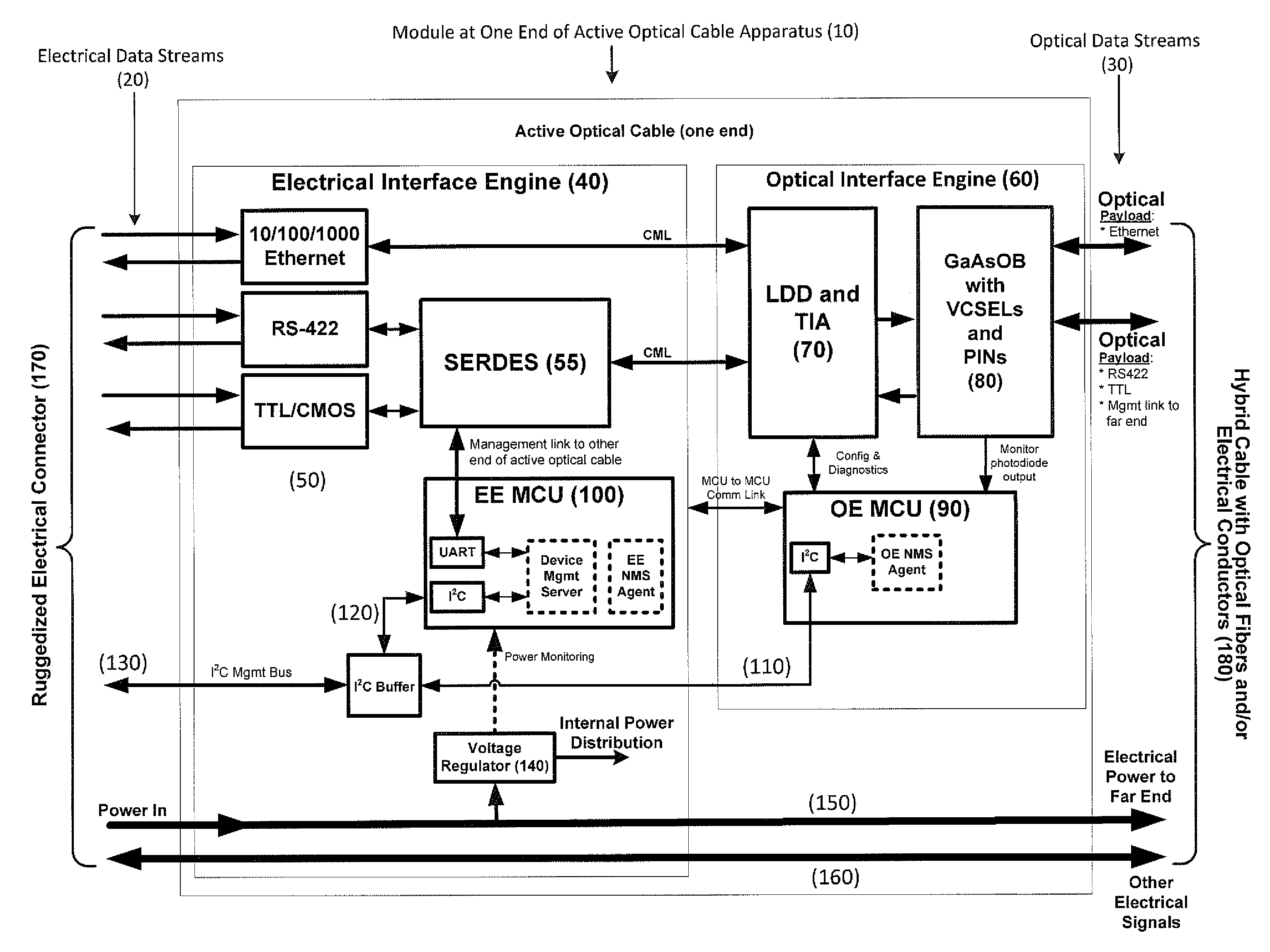
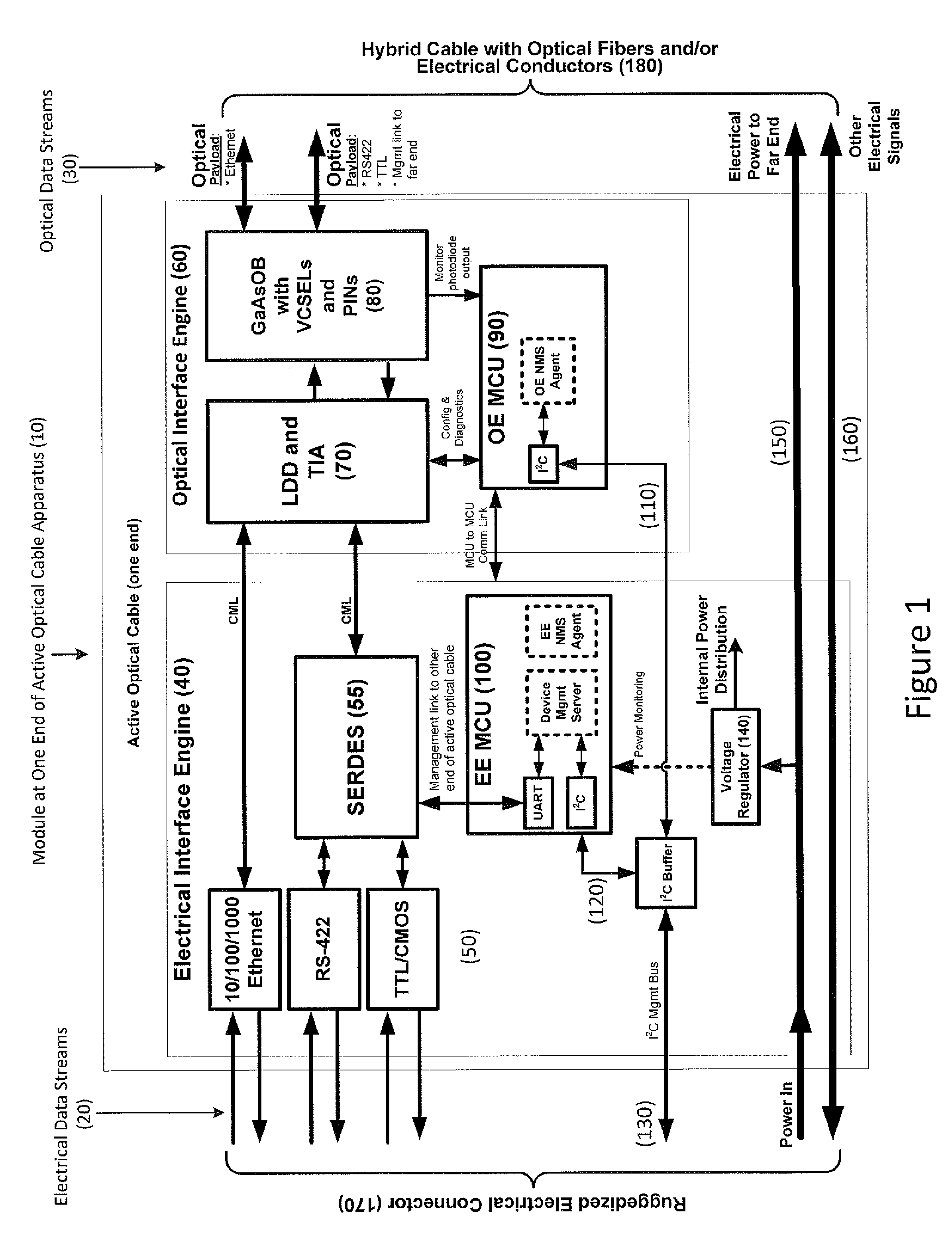
[0101]An apparatus for a modular implementation of multi-function active optical cables, particularly for harsh environment applications is provided. The apparatus may be implemented in accordance with embodiments disclosed herein in a modular building block embodiment as illustrated in FIG. 1. In particular, FIG. 1 illustrates an example of a module at one end of an active optical cable apparatus 10 in which multiple electrical data streams 20 may be converted into optical data streams 30 and vice versa. Modular functionality blocks are illustrated in FIG. 1 for simplicity. For example, an electrical interface engine 40 and optical interface engine 60 are shown. The electrical interface engine 40 may have electrical media convertors 50, SERDES 55, microcontrollers (MCU) 100, and voltage regulators and isolation 140. The optical interface engine 60 may have laser diode drivers (LDD) and transimpedance amplifiers 70, optical benches, VCSELs, and PIN photodetectors 80, and microcontro...


PUM

PropertyMeasurementUnit
Fractionaaaaaaaaaa
Temperatureaaaaaaaaaa
Lengthaaaaaaaaaa

Abstract

Apparatus enabling modular implementation of active optical cable (AOC) with multiple integrated functions including: integration of different types of data on the AOC via media conversion; distribution of electrical power over the AOC; electrical multiplexing data channels for optical fibers; integration of voltage regulators enabling AOC operation at different supply voltages; integration of voltage regulators to provide stable, low noise power source; ruggedized, blind-mateable electrical connectors; integration of electronics and optoelectronics inside a connector backshell; implementation of health monitoring and test channel enabling monitoring, test, and control of both ends of the AOC and monitoring and control of upstream systems and components; and enabling a form, fit, function replacement of existing electrical cables to improve SWaP, electromagnetic interference resiliency, length-bandwidth product, electromagnetic pulse resistance, signal integrity, system reliability, testability and maintenance. AOCs are customized for different connectors, pin-outs, electrical data combinations, power distribution and power supplies with minimal redesign/requalification.

Description

CROSS REFERENCE TO RELATED APPLICATIONS[0001]This application claims the benefit of U.S. Provisional Application Ser. No. 61 / 747,295 entitled “Apparatus for Modular Implementation of Multi-Function Active Optical Cables” filed Dec. 29, 2012 and U.S. Provisional Application Ser. No. 61 / 747,349 entitled “Method and Apparatus for Modular Design, Manufacturing and Implementation of Multi-Function Active Optical Cables” filed Dec. 30, 2012. Both of the above-referenced provisional applications are hereby incorporated herein by reference in their entireties.BACKGROUND OF THE INVENTION[0002]This invention relates generally to electrical and / or optical cables. More specifically, the present invention relates to active optical cables, particularly for use in aerospace, military, and / or industrial applications in harsh environments.[0003]Most interconnects in harsh environments, particularly for aerospace, military, and / or industrial applications, may be implemented using electrical cables. U...

Claims


Application Information

Patent Timeline
IPC IPC(8): H04B10/2581H04B10/077
CPCH04B10/077H02G1/14H04B10/2581G02B6/3817G02B6/3885G02B6/4269G02B6/4293G02B6/4416G02B6/4471Y10T29/49117H04B10/038H04B10/071H04B10/0791H04B10/0795H04B10/0797H04B10/807
Inventor LOUDERBACK, DUANE
Owner ZEPHYR PHOTONICS
Why Eureka
Try Eureka