Vehicle power-supply unit

Active Publication Date: 2014-10-09
MITSUBISHI ELECTRIC CORP
View PDF3 Cites 4 Cited by
  • Summary
  • Abstract
  • Description
  • Claims
  • Application Information

AI Technical Summary

Benefits of technology

[0008]The invention was devised to solve the problems discussed above and has an object to provide a vehicle power-supply unit capable o

Problems solved by technology

This vehicle power-supply system requires a voltage transducer to handle power supplies having different voltages and has

Method used


Image

  • Vehicle power-supply unit
  • Vehicle power-supply unit
  • Vehicle power-supply unit

Examples


first embodiment

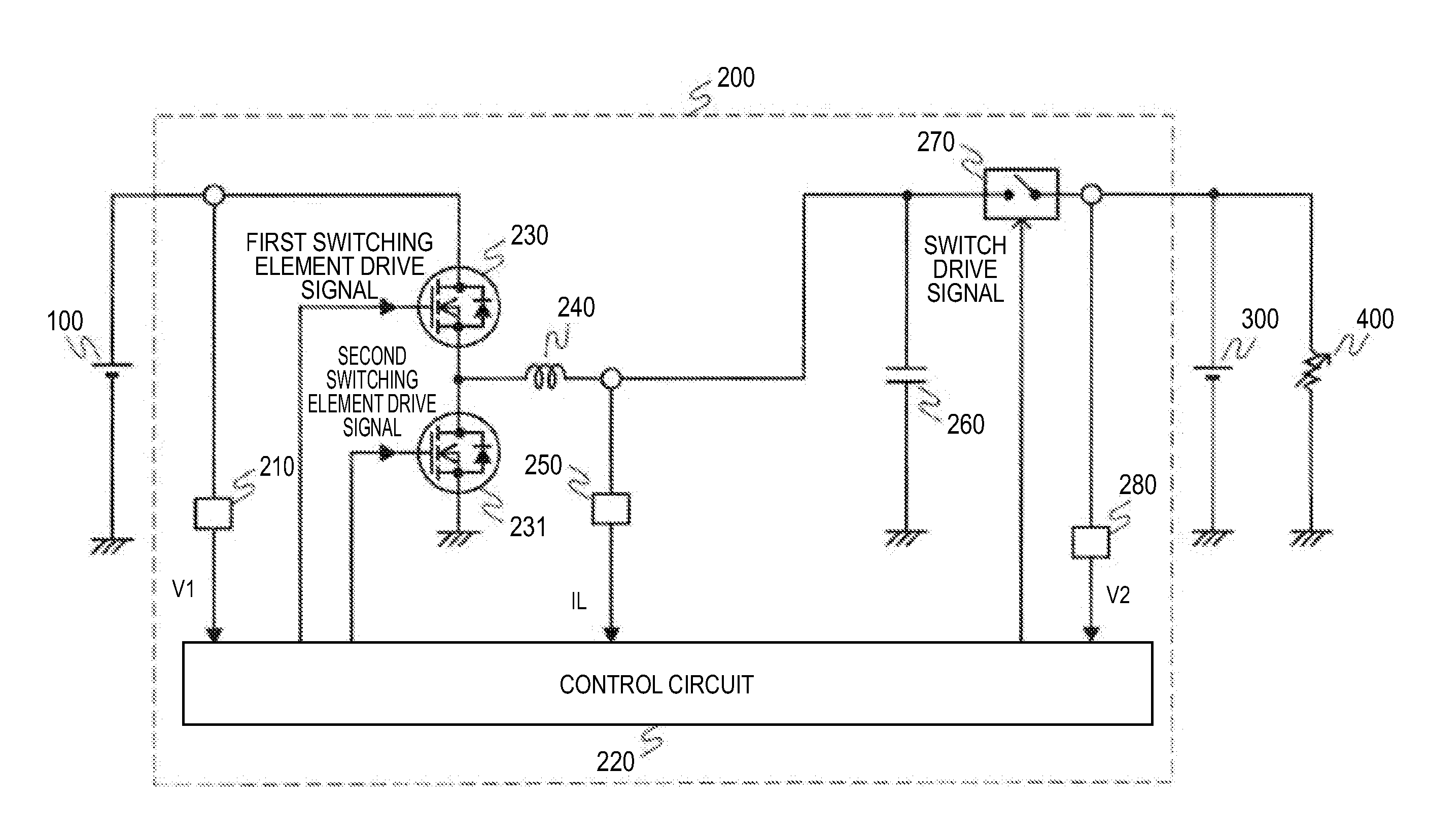
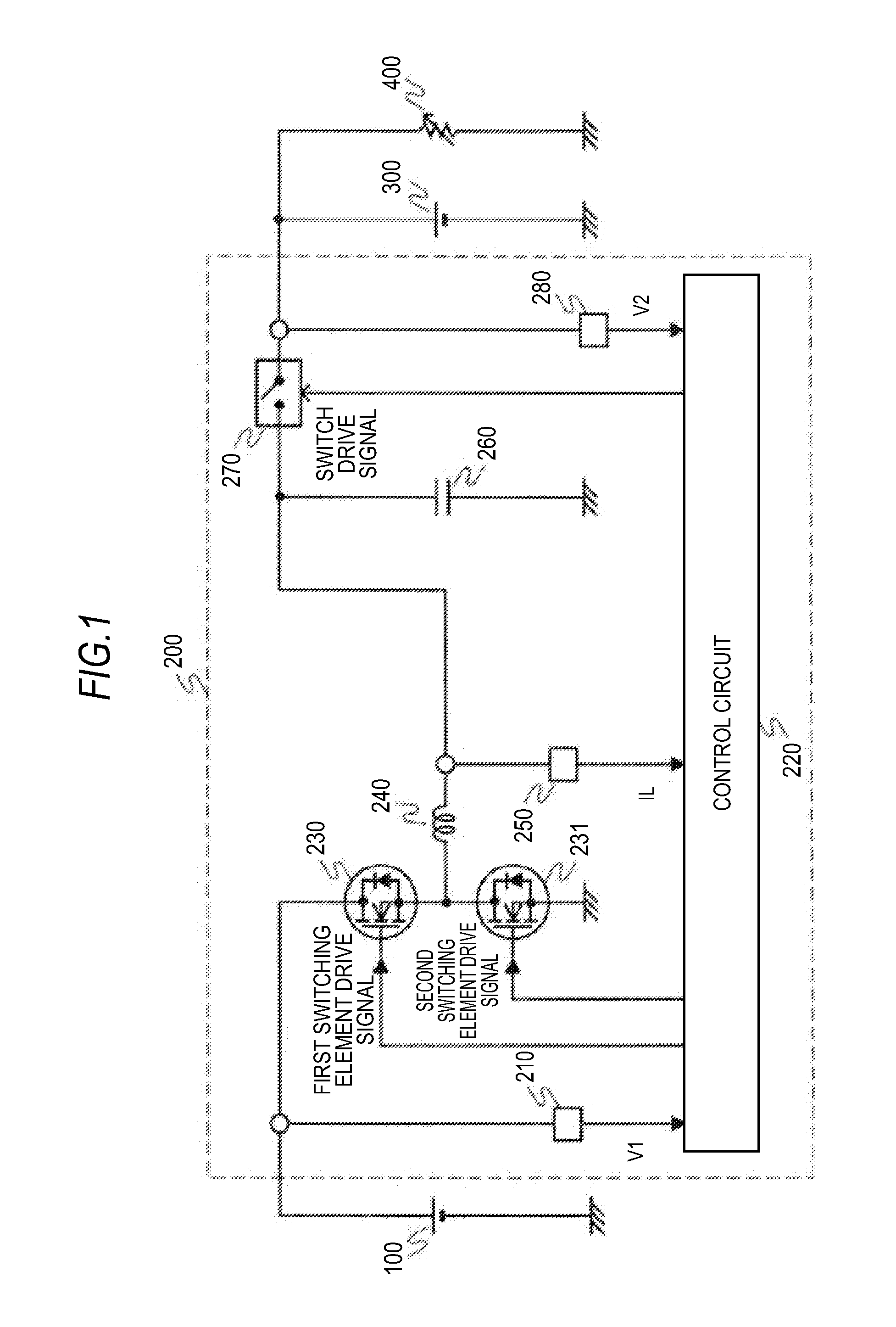
[0021]FIG. 1 is a view showing a configuration of a vehicle power-supply unit according to a first embodiment of the invention. A first power supply 100 of FIG. 1 is a storage cell, for example, an electric double layer capacitor or a lithium-ion battery, and is connected to a generator, such as an alternator including a rectifier and an MG (Motor Generator) (not shown in the drawing). The first power supply 100 is charged to a predetermined voltage value V1 by the generator and supplies a current to an in-vehicle electric load 400 via a voltage transducer 200. The voltage transducer 200 transforms the voltage value V1 of the first power supply 100 to a DC voltage value V2 and outputs the transformation result. A second power supply 300 is a storage cell similar to the first power supply 100, for example, a lead storage battery, and is connected to an output side of the voltage transducer 200 together with the vehicle electric load 400.

[0022]The voltage transducer 200 is, for exampl...

second embodiment

[0054]FIG. 4 is a view showing a configuration of a vehicle power-supply unit according to a second embodiment of the invention. Differences from FIG. 1 are that a diode 271 disposed with its anode on the side of the reactor 240 and its cathode on the output terminal side of the voltage transformer 200 is connected in parallel with the switch element 270 and that a diode current detection portion 272 that detects a current flown through the diode 271 is provided. The rest is the same as the configuration of FIG. 1.

[0055]The control flow of the voltage transducer 200 since the vehicle power-supply unit configured as in FIG. 4 is started till the voltage value V2 of the second power supply 300 is controlled will be described using the flowchart of FIG. 5.

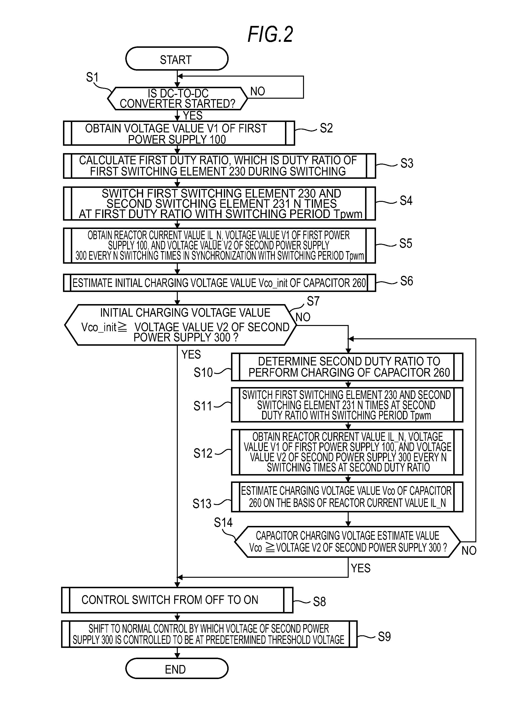
[0056]Contents of Step S1 through Step S11 in the flowchart of FIG. 5 are the same as the contents of Step S1 through Step S11 in the flowchart of the first embodiment depicted in FIG. 2, and a description of these steps is omitted he...

third embodiment

[0061]FIG. 6 is a view showing a configuration of a vehicle power-supply unit according to a third embodiment of the invention. In this configuration, the voltage transducer 200 of the first embodiment shown in FIG. 1 is changed to a step-up DC-to-DC converter.

[0062]In the voltage transducer 200 of the third embodiment, the plus terminal of the first power supply 100 and the plus terminal of the second power supply 300 are connected via the reactor 240, the second switching element 231, and the switch element 270. The plus terminal of the first power supply 100 is connected to one end of the reactor 240 and the drain side of the first switching element 230 the source side of which is connected to the ground is connected to the other end of the reactor 240. The source side of the second switching element 231 is connected to the other end of the reactor 240 and the drain side of the second switching element 231 is connected to one end of the switch element 270. Further, the other end ...


PUM


Abstract

A vehicle power-supply unit has chargeable and rechargeable first power supply and second power supply connected to a voltage transducer at input and output terminals, respectively, and a switch element connected between the output terminal of the voltage transducer and the second power supply. By controlling a rector current flown through a reactor connected to at least two switching elements at one end when the voltage transducer is started, a capacitor connected between the other end of the reactor and the ground is charged, and the switch element is brought in a connection state according to a charging voltage of the capacitor and a voltage value of the second power supply. Consequently, a vehicle power-supply unit can protect the elements by preventing a rush current during a backflow and reverse connection and at start-up.

Description

BACKGROUND OF THE INVENTION[0001]1. Field of the Invention[0002]The present invention relates to a vehicle power-supply unit configured to prevent a rush current in a vehicle power-supply system since power activation till start-up.[0003]2. Description of the Background Art[0004]With the aim of improving fuel efficiency for a reduction of environmental burdens, there is a vehicle power-supply system requiring at least two independent power supplies to increase power generation efficiency of a generator and to use regenerative energy during deceleration. This vehicle power-supply system requires a voltage transducer to handle power supplies having different voltages and has a problem of how to prevent a rush current at start-up and protect elements from a backflow and during reverse connection.[0005]PTL 1 discloses a system adopting a step-up DC-to-DC converter, in which protection against reverse connection is provided, and also a rush current is prevented and elements are protected...

Claims


Application Information

Patent Timeline
IPC IPC(8): H02M3/158B60L11/18B60L50/16
CPCB60L11/18H02M3/158H02M3/156H02M3/1588B60L2210/10B60L2270/20B60L50/16Y02T10/72Y02T10/7072Y02T10/70
Inventor UBUKATA, TAKAYUKIKIHARA, NOBUHIRO
Owner MITSUBISHI ELECTRIC CORP
Why Eureka
Try Eureka