High-voltage insulation device for charged-particle optical apparatus

a technology of optical apparatus and high-voltage insulation, which is applied in the direction of instruments, beam deviation/focusing by electric/magnetic means, mass spectrometers, etc., can solve the problems of high mass and cost, high risk of breakage, and high mechanical stability, and achieve good electrical insulation and high mechanical stability. , the effect of low weigh

Active Publication Date: 2014-07-17
IMS NANOFABTION
View PDF92 Cites 19 Cited by
  • Summary
  • Abstract
  • Description
  • Claims
  • Application Information

AI Technical Summary

Benefits of technology

[0006]It is an aim of the invention to provide a high-voltage insulation device which ensures high mechanical stability and good electrical insulation while at the same time allo

Problems solved by technology

For such a setup, it is necessary to provide for high-voltage feedthroughs for the high-voltage supply lines that are used to for high-voltage components, which are bulky and expensive.
However, conventional ins

Method used


Image

  • High-voltage insulation device for charged-particle optical apparatus
  • High-voltage insulation device for charged-particle optical apparatus
  • High-voltage insulation device for charged-particle optical apparatus

Examples


Embodiment Construction

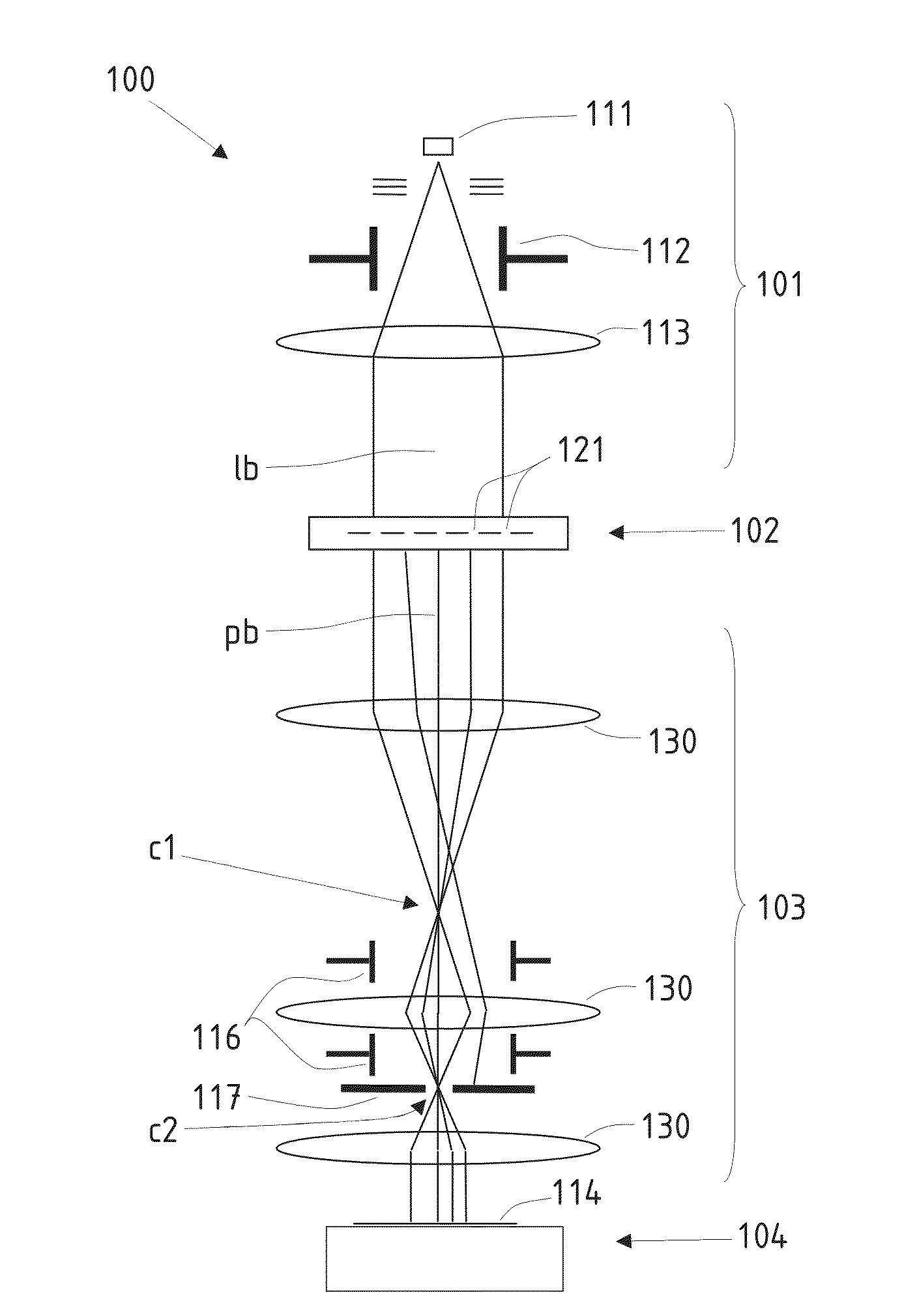
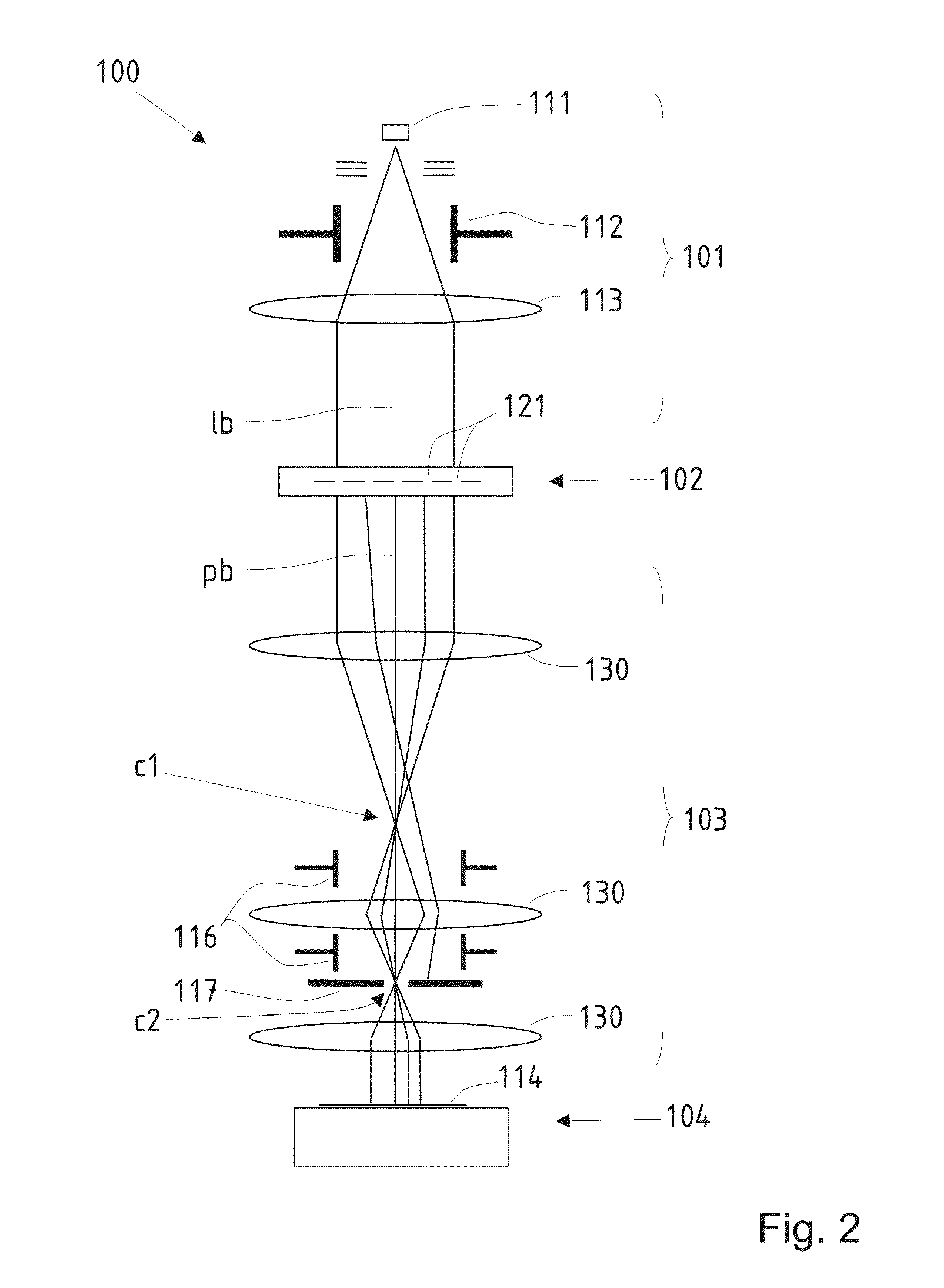
[0025]FIG. 1 shows a particle-beam-based processing tool according to the invention, comprising an optical column; the optical column is shown in greater detail in FIG. 2. The preferred embodiment of the invention discussed in the following implements a particle-beam exposure apparatus of the type referred to as PML2. The PML2 architecture includes a pattern definition (PD) system defining the structures to be exposed / processed at the target, and a large-reduction projecting system. It is to be appreciated that the invention is not restricted to the following embodiments or the particular layout of PD systems, which merely represent examples of possible implementations of the invention; rather, the invention is suitable for other types of processing systems that employ a particle-beam and projection of the features of a PD system onto a target to be processed.

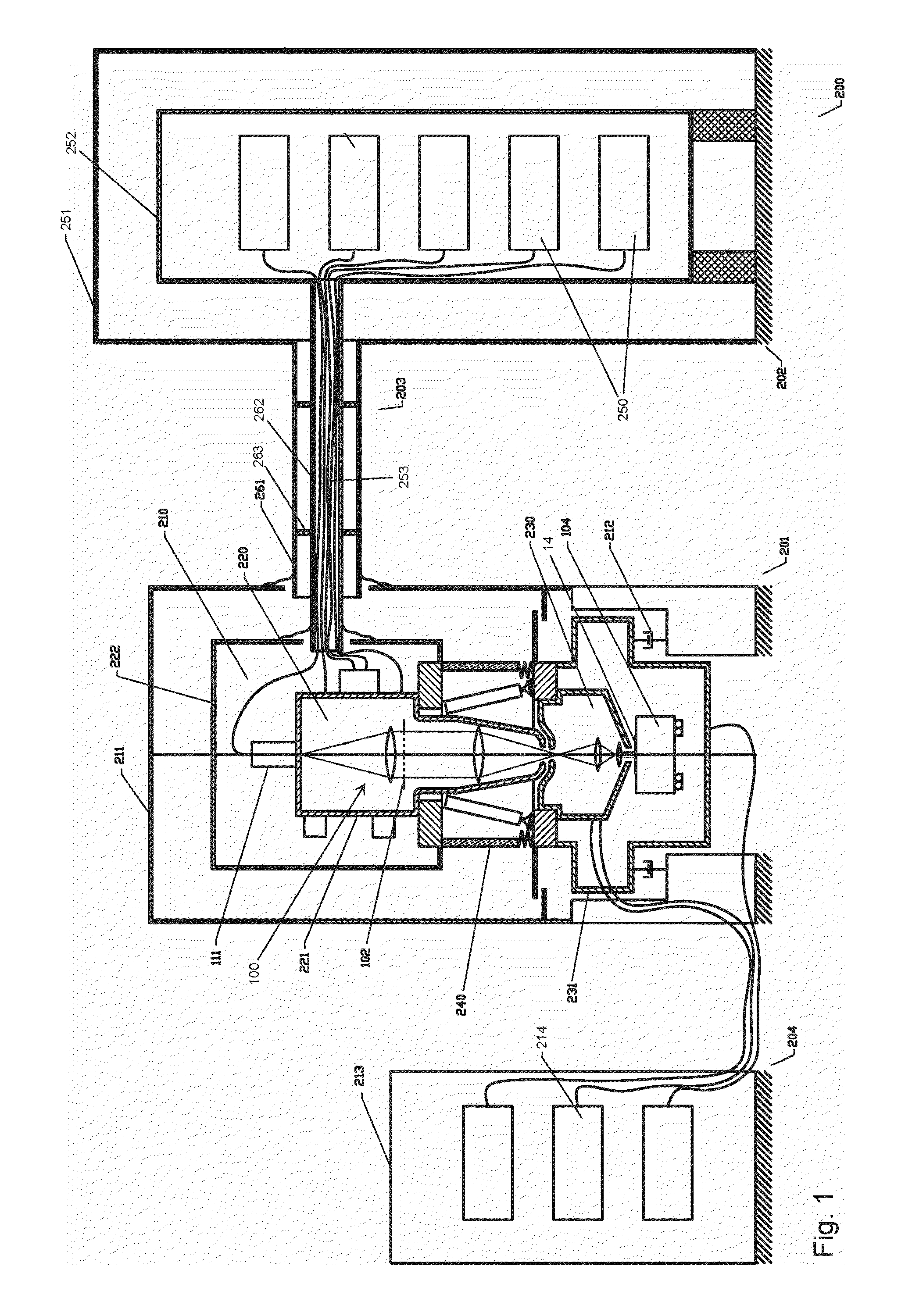
[0026]The schematic sectional view shown in FIG. 1 depicts an overview of the architecture of the tool setup 200 according to...


PUM


Abstract

A high-voltage insulation device (300) for use in a charged-particle optical apparatus comprises a plurality of rigid pillars (320) made of electrically insulating material. These pillars (320) are arranged around a central passage (310) which traverses the insulating device along its longitudinal axis (L), and the two ends of each pillar are configured to be respectively fixed to two separate electrostatic housings (221, 231) of the charged-particle optical apparatus by means of two respective end plates (311, 312), with the pillars (320) being oriented at an angle so as to be inclined with regard to said longitudinal axis (L). Advantageously, the pillars are mechanically adjustable with regard to their effective length, and each pillar (320) is arranged outside the central passage with its two ends at either of the first and second end plates (311,312), preferably in a zig-zag arrangement.

Description

CROSS-REFERENCE TO RELATED APPLICATIONS[0001]This application claims the benefit of European Patent Application No. 13151585.0, filed Jan. 17, 2013, the disclosure of which is hereby incorporated by reference as if set forth in full herein.FIELD OF THE INVENTION[0002]The present invention relates to a high-voltage insulation device for use in a charged-particle optical apparatus, comprising a construction of electrically insulating material. Furthermore, the invention relates to a charged-particle optical apparatus comprising an electro-optical column and at least two electrostatic housings which surround respective sections of the electro-optical column and are configured for being applied different electrostatic potentials. The high-voltage insulating device is configured for separating two electrostatic housings of the mentioned kind.BACKGROUND[0003]In a charged-particle optical apparatus of the mentioned kind charged particles such as electrons or ions are brought to high kineti...

Claims


Application Information

Patent Timeline
IPC IPC(8): H01B17/14H01J37/147
CPCH01J37/147H01B17/14H01J37/023H01J37/04H01J37/15H01J37/3177H01J2237/036H01J2237/038H01J2237/1502B82Y10/00B82Y40/00
Inventor PLATZGUMMER, ELMARCHYLIK, ANDREASKRATZERT, GERALDOBERLEITNER, ROMAN
Owner IMS NANOFABTION
Why Eureka
Try Eureka