System and Method for Estimating the Position and Orientation of an Object using Optical Beacons

a technology of optical beacons and positioning devices, applied in the field of system and method for estimating the position and orientation of objects using optical beacons, can solve the problems of inconvenient positioning, large working area, and difficulty in recognizing markers from different orientations and ambient lighting conditions, so as to increase the accuracy of position measurements and identify beacons quickly on demand

Inactive Publication Date: 2014-07-17
MURRAY KEVIN HUGH
View PDF0 Cites 40 Cited by
  • Summary
  • Abstract
  • Description
  • Claims
  • Application Information

AI Technical Summary

Benefits of technology

[0020]The advantage of the first improvement is that the system can quickly identify beacons on demand, without interrupting other vehicles that may be using the beacons. The identification process requires no additional equipment because it takes advantage of the random pixel access feature common in low-cost image sensors.
[0021]The advantage of the second improvement is that the beacons can he lowered underground so that the do not interfere with other processes occurring in the working area. This allows beacons to he placed within the working area instead of confined to the perimeter, as done by others in the prior art. Having beacons within the working area increases the precision of the position measurements and / or allows the system to be applied to larger areas. Beacons can also be individually lowered based on the position and intended path of the vehicle in order to avoid collisions with the vehicle. This is especially advantageous when the vehicle is performing lawn maintenance (e.g. mowing and leaf removal) because it allows the vehicle to pass directly over the beacons.
[0022]The advantage of the third improvement is that the system uses the atmosphere as a filter for extraterrestrial light. This is beneficial because sunlight is by far the largest source of optical noise in this type of system,

Problems solved by technology

A significant disadvantage of the resection technique is that the error in the calculated position is linearly dependent on the distance to the reference points.
This may be prohibitively expensive for very large working areas.
A significant disadvantage of this approach, however, is that the marker may be difficult to recognize from different orientations and in different ambient lighting conditions.
A disadvantage of this method is that detecting artificial light sources can be difficult due to the high-brightness of other sources of light in the environment, such as sunlight and artificial illumination.
The disadvantage of this method is that it requires a specially designed camera system.
The ability to sample every pixel at 12,000 hertz may be prohibitively expensive, especially for as positioning system that requires one to several million pixels in order to provide direction measurements at sufficient precision.
While these methods work well to distinguish beacon light front environmental light, they lack the ability to identify individual beacons.
However, as Farwell notes, the initial beacon identifications cannot he determined this way.
The system can only identify beacons that it has previously identified, and the motion of the robot cannot have greatly altered the position of the beacons within image frames.
The first disadvantage is that it may take a substantial amount of time to identify beacons, especially if a matching attempt needs to be made for every beacon in the environment.
The second disadvantage is that this process would interrupt other robots using the beacons.
Modulating the emissions of beacons is a useful method of distinguishing beacons from the environment, but it may not be sufficient in some environments.
Outdoor areas during the day are an especially challenging environment, simply due to the magnitude of sunlight.
One issue with this idea is that some outdoor environments do not or cannot have sufficient vertical structures.
While this keeps the beacons from interfering with anything in the working environment, it may be impractical for large areas or areas with widely varying terrain.

Method used


Image

  • System and Method for Estimating the Position and Orientation of an Object using Optical Beacons
  • System and Method for Estimating the Position and Orientation of an Object using Optical Beacons
  • System and Method for Estimating the Position and Orientation of an Object using Optical Beacons

Examples


first embodiment

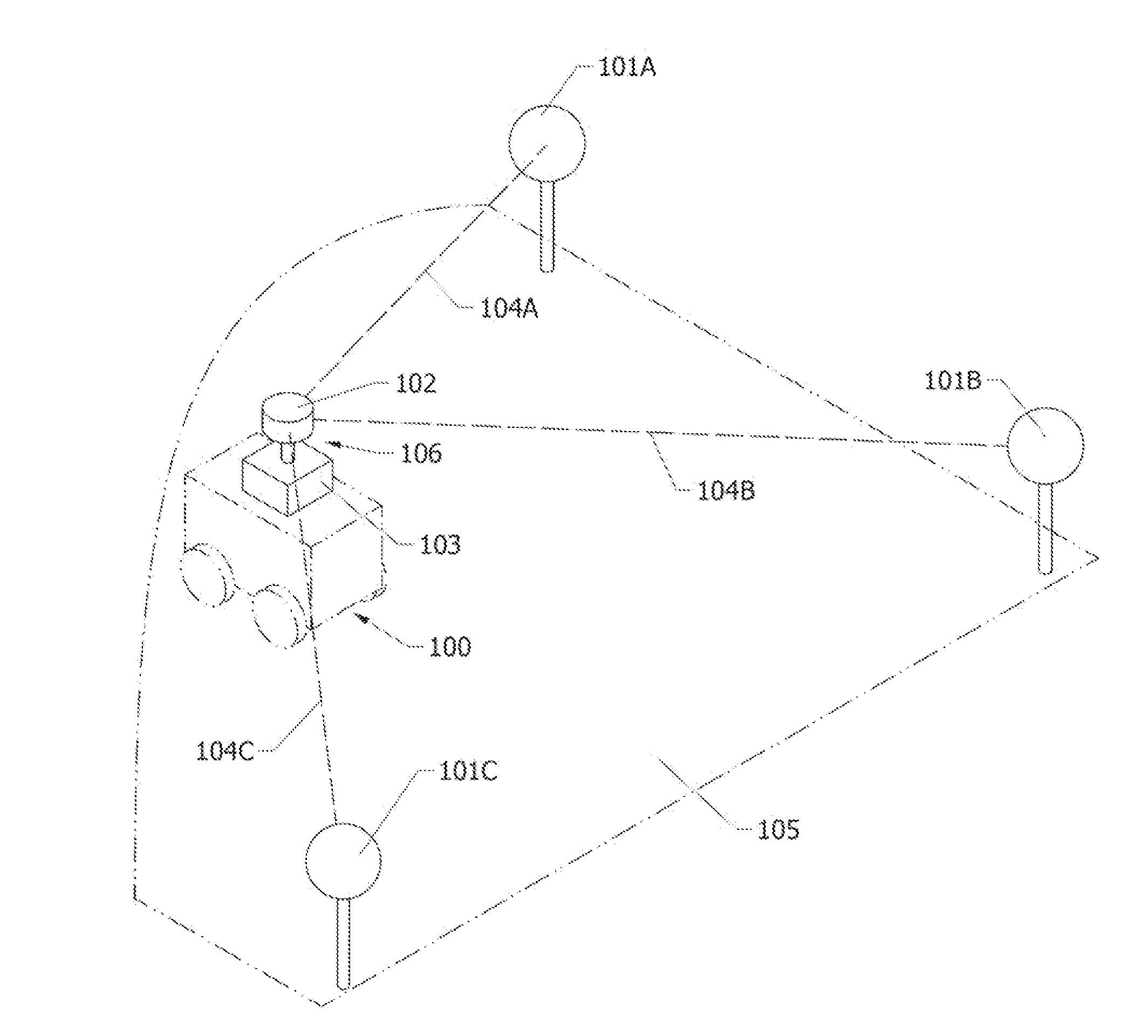
FIGS. 1, 4, 5A, 5B, 5A through 5F, and 7—First Embodiment

[0042]The first embodiment improves upon the foundation b providing as robust design and method for both detecting and identifying beacons. The image sensor(s) within the imaging system 102 are of a type that allows random pixel access. The random pixel access feature allows individual pixels or small groups of pixels to be sampled at a rate that is significantly higher than the full-frame rate of the camera. For example, a typical image sensor with this capability may have a 60 hertz frame rate, but allow small groups of pixels to be sampled at 400 hertz or more. Sampling a small portion of the image sensor is often called windowing or region of interest mode, Henceforth, the frequency that full images (i.e. all pixels) are sampled will he referred to as the full-frame rate and the frequency that a small group of pixels are sampled will be referred to as the partial-frame rate. The partial-frame rate is at least twice the ful...

second embodiment

FIGS. 8, 9, and 10—Second Embodiment

[0061]The second embodiment improves upon the foundation by allowing the beacons to he distributed within the working area without interfering with processes that occur within the working area. This is achieved by burying beacons underground and providing a means for them to rise above ground when needed, as well as a means of communication with the beacons.

[0062]FIGS. 8A, 8AS, 8B, and 8BS show a particular design for a beacon that can raise itself above ground on command. FIGS. 8A and 8AS show a perspective view and a section view, respectively, of the beacon in a lowered position. In the lowered position, the top of the beacon is flush with the ground. FIGS. 8B and 8BS show a perspective view and a section view, respectively, of the beacon in a raised position.

[0063]The beacon is raised and lowered by means of as linear actuator, shown in FIGS. 8AS and 8BS. The linear actuator is composed of an electric motor 805, a screw 807, a fixed tube 802, ...

third embodiment

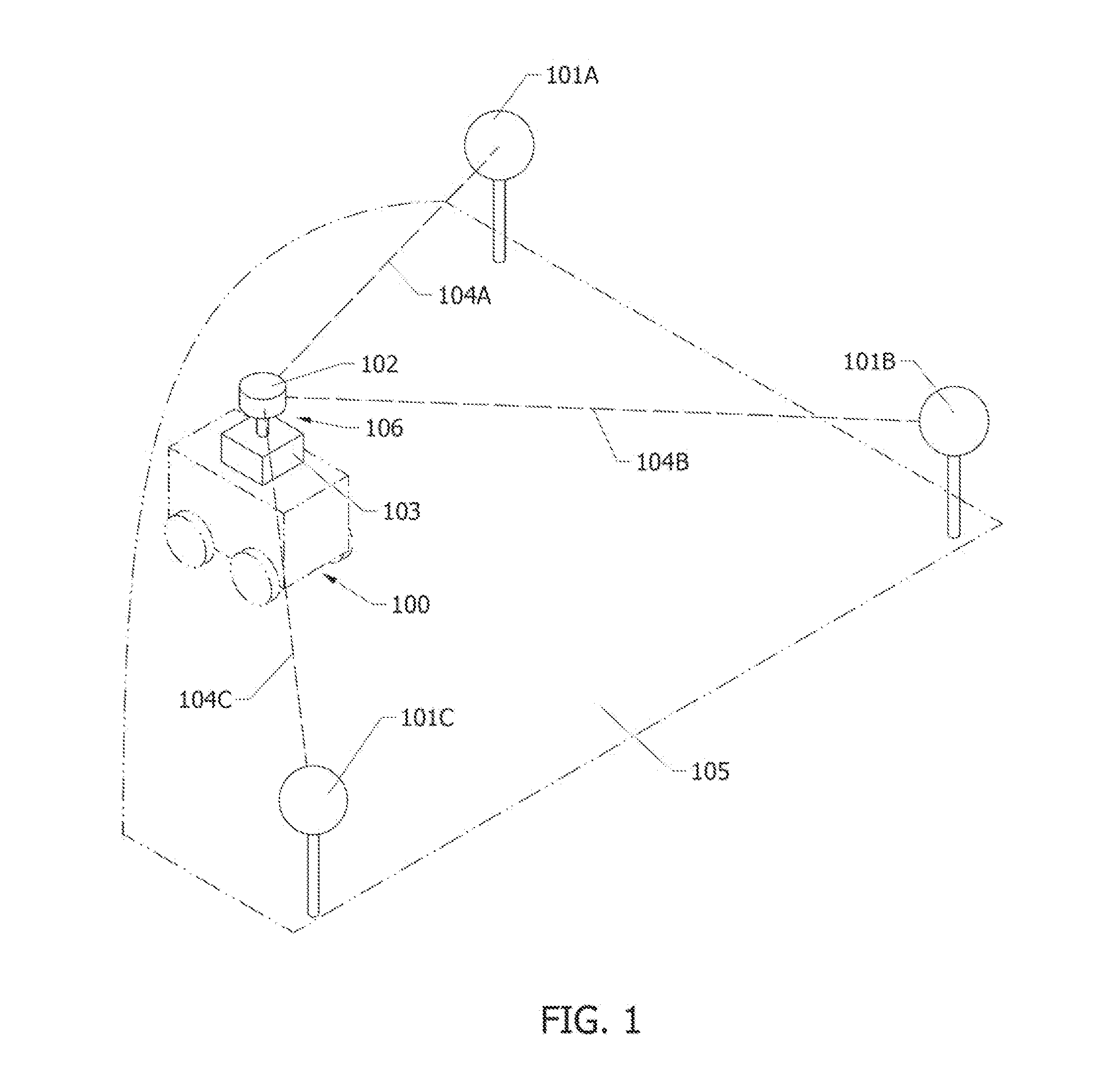
FIGS. 1, 2, 3 and 11—Third Embodiment

[0077]The third embodiment improves upon the foundation by increasing the signal-to-noise ratio of the beacons. This is achieved by using the atmosphere to filter extraterrestrial light.

[0078]FIG. 11A shows the spectral density of light emitted by the sun, measured above the atmosphere. The x-axis represents the wavelength of light (in terms of micrometers) and the y-axis represents light intensity (in terms of kilowatts per meter squared, per micrometer). FIG. 11B shows the spectral density of light emitted by the sun, measured at sea level. The axes of 11B are the same as FIG. 11A.

[0079]As can be seen from FIGS. 11A and 11B, the light intensity at sea level is generally lower across the spectrum, as compared to the light intensity above the atmosphere. The light intensity is especially low at and around wavelengths of 0.76, 0.94, 1.13, and 1.38 micrometers (indicated by reference, numerals 21, 22, 23, and 24, respectively). These are water and ...


PUM


Abstract

A system and method for determining the position and orientation of an object within an environment using optical beacons placed at known locations within the environment. The optical beacons are received by an imaging device mounted on the object to be positioned, The system derives the position and orientation of the object from data associated with the pixel locations of the beacons within images, the identity of the beacons within images, and the positions of the beacons within the environment. In one embodiment, the optical beacons emit signals that are patterned in such a way that they appear as a first signal when sampled a low sampling rate and appear as a second signal when sampled at a high sampling rate. The first signal is the same for each beacon, and is used to distinguish beacons from other sources of light in the environment. The second signal is different for each beacon, and is used to identify beacons. In another embodiment, the optical beacons are installed underground and rise on command. In another embodiment, the optical beacons may also emit light within an absorption band of the atmosphere m order to improve the signal to noise ratio of the beacons.

Description

CROSS-REFERENCE TO RELATED APPLICATIONS[0001]This application claims the benefit of provisional patent application Ser. No. 61 / 753,646, filed Jan. 17, 2013 by the present inventor.FIELD OF THE INVENTION[0002]The present invention relates to systems which provide location and orientation information to mobile vehicles. More particularly, the present invention relates to systems which obtain position and orientation information based on measured directions to fixed objects with known locations.BACKGROUND THE INVENTION[0003]The ability to precisely measure position is an important feature in many mobile robotic applications. Two common classes of positioning techniques are trilateration and resection (often called triangulation). Both techniques allow a mobile robot to determine its position based on measurements to reference points of known position. Trilateration uses the distances measured to reference points, generally using the time of flight of some signal of known propagation sp...

Claims


Application Information

Patent Timeline
Patent Type & Authority Applications(United States)
IPC IPC(8): H04N7/18G01C3/02
CPCG01C3/02H04N7/181G01S5/16G05D1/0234
Inventor MURRAY, KEVIN HUGH
Owner MURRAY KEVIN HUGH
Why Eureka
Try Eureka