The wide external
diameter of the prior art catheter may cause (sub)obstruction of the
blood flow.
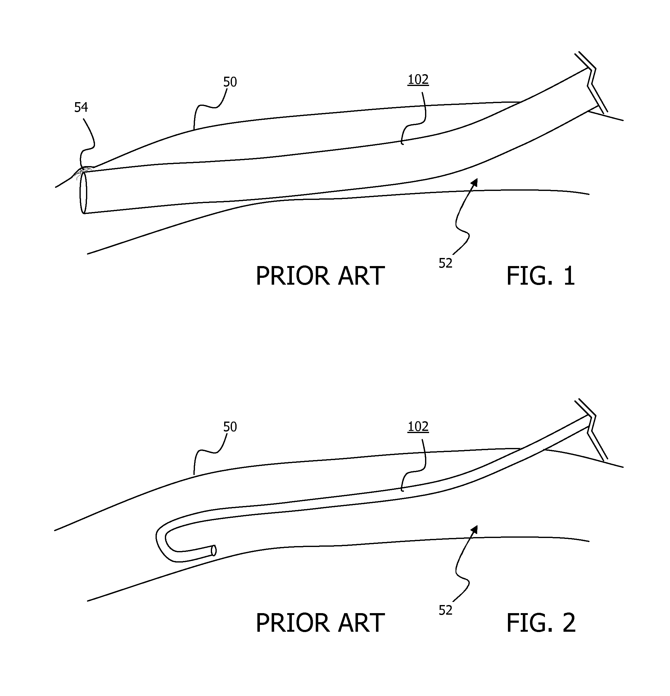
Additionally, the position of the catheter tip cannot be stabilised with respect to the wall of the vessel, causing a risk of
dislocation of the catheter's distal tip and possible dysfunction of the catheter.
A further
disadvantage of conventional catheters is damage to the vessel wall during advancement.
While pushing the catheter inside a vessel lumen, the catheter's tip can either cause endothelial wall lesions or friction initiating the
cascade of
blood clotting, or can be deviated by a septum, causing malfunctioning or obstruction of the catheter.
In adults, introducing the catheter into the sinus through a standard
skull burr hole is technically cumbersome, since an
oblique angle is necessary to prevent endothelial laceration of the opposite venous sinus wall and to realize a correct orientation of the catheter (i.e. ante- or retrograde to the
blood stream).
However, the thickness of the
skull bone, requires a wide bore hole to achieve an angle sufficiently oblique.
Also, in the pediatric and adult
population, the positioning of the subgaleal trajectory of the shunt
system is quite difficult in order to prevent kinking of the tubing and to avoid stress causing displacement of the sinusal catheter.
This siphoning effect can cause over-drainage of
cerebrospinal fluid causing intracranial hypotension.
In the
acute stage, this over-drainage can cause collapse of the brain's ventricles and acute subdural
hematoma.
In the ventriculo-atrial and ventriculo-peritoneal shunt patients, the internal jugular veins are bypassed, therefore more complex valves (
variable resistance valves or flow regulating valves) and anti-
siphon devices are utilised in the art, making a cerebrospinal fluid shunt much more complex, more vulnerable, and more expensive.
Despite these technical improvements, a small group of patients still experience symptoms due to non-physiological cerebrospinal fluid evacuation and therefore non-physiological intracranial pressures.
Ventriculo-atrial and ventriculo-peritoneal shunts are easily obstructed causing insufficient cerebrospinal fluid evacuation and therefore intracranial hypertension.
Also, in growing children, the peritoneal catheter's tip can be retracted into the
subcutaneous fat or the atrial catheter's tip into the superior caval
vein causing insufficient cerebrospinal fluid evacuation.
Ventriculo-atrial and ventriculo-peritoneal shunts have a
high rate of bacterial shunt infections, with risk of bacterial
meningitis or ventriculitis or cerebritis, possibly with livelong morbidity or even mortality risk.
Disadvantages associated with ventriculosinus shunts include their obstructive size that may cause a raised
venous pressure inside the dural venous sinus, may reduce the
blood flow speed and thus the risk of clotting of the blood inside the dural venous sinus (sinus
thrombosis).
Additionally, the catheter cannot be stabilized onto the sinus's wall, causing a risk of
dislocation of the catheter's distal tip and possible dysfunction of the cerebrospinal fluid shunt.
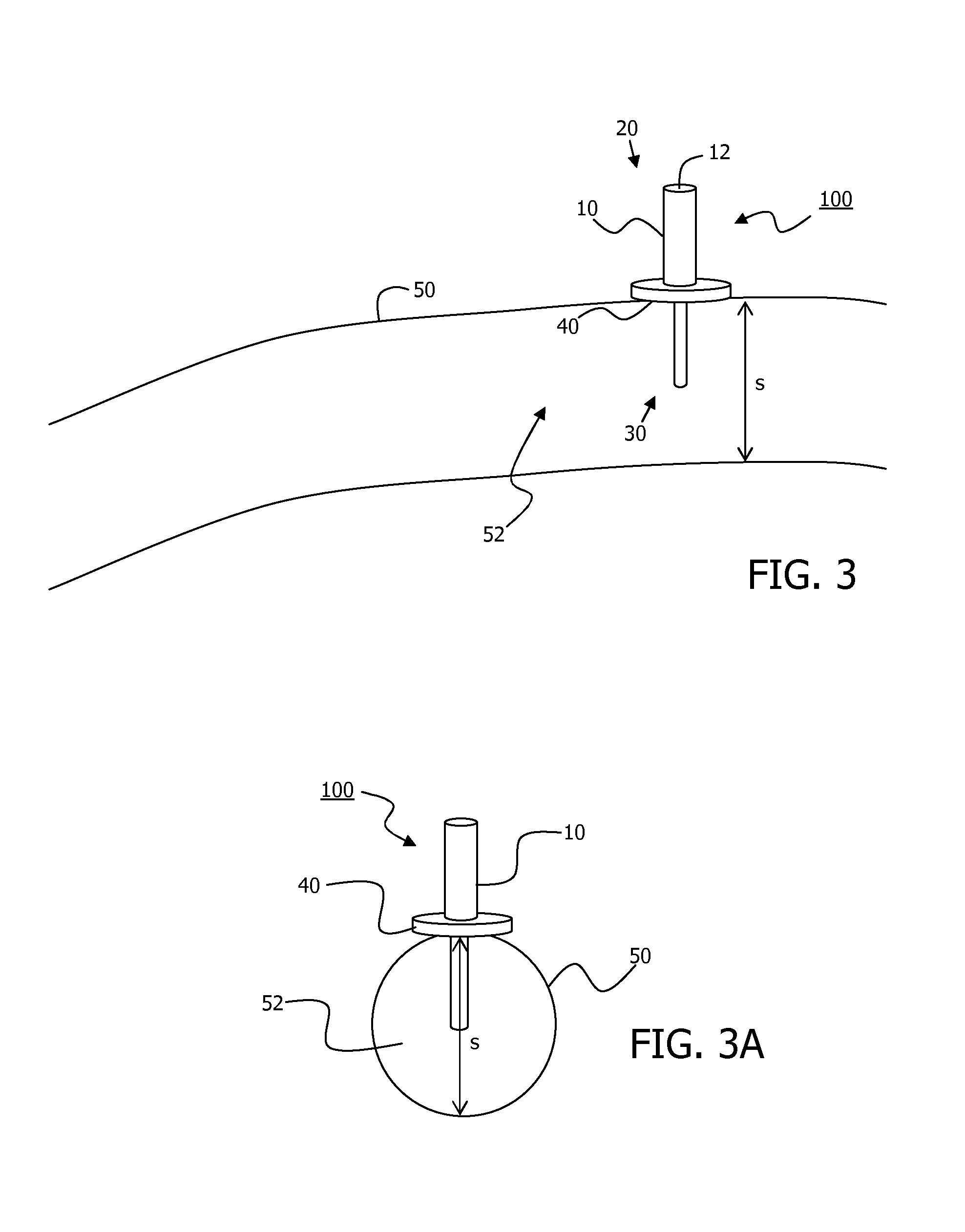
Moreover, the position of catheter tip cannot be stabilised inside the sinus's lumen; it should be localised in the center of the sinus's diameter.
The catheter is more likely to be blocked by the endothelial layer covering the internal wall of the dural venous sinus, thus causing a total obstruction of the cerebrospinal fluid shunt.
Further, the catheter tip
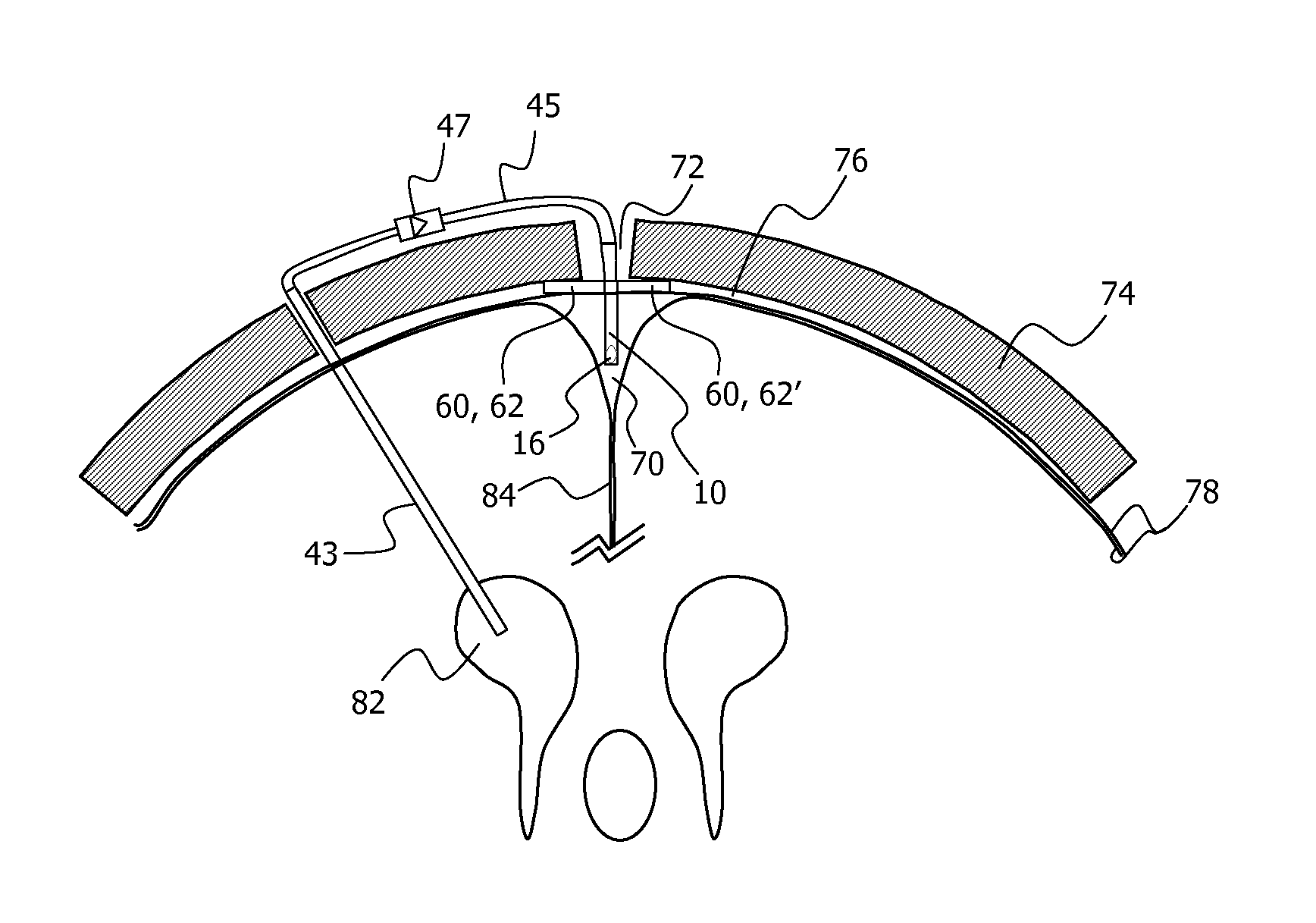
lying against the internal wall of the venous sinus cannot fully profit from the impaction effect created by the velocity of the blood flow inside the dural venous sinus as the velocity of this blood flow is maximal at the center of the sinus's diameter and minimal against the sinus's inside wall.
While advancing the catheter inside the dural venous sinus with an intrasinusal length of 20 to 50
millimeter, the catheter's tip can easily either cause endothelial wall lesions increasing the risk of
blood clotting, or can be deviated by an intrasinusal septum, causing malfunctioning or obstruction of the cerebrospinal fluid shunt.
This increases the risk of important
blood loss, the risk of aspiration of air inside the sinus possibly causing an
air embolism and the risk of
invagination of the endothelial layer causing obstruction to the blood flow inside the dural venous sinus.

