Heat exchanger of an internal combustion engine

a technology of heat exchanger and internal combustion engine, which is applied in the direction of heat exchanger recovery, exhaust treatment, stationary tubular conduit assembly, etc., can solve the problems of high thermal and mechanical stress of heat exchanger, and the application of heat exchanger in vehicles is also associated with high stress, so as to improve the service life of the mount

Inactive Publication Date: 2014-07-31
EBERSPACHER EXHAUST TECH GMBH & CO
View PDF10 Cites 10 Cited by
  • Summary
  • Abstract
  • Description
  • Claims
  • Application Information

AI Technical Summary

Benefits of technology

[0007]The present invention is based on the general idea of mounting the at least one spiral tube on the housing via such an elastic outer mounting layer. Such a spiral tube is arranged in this case in the gas path and extends helically in relation to a central longitudinal axis of the housing. A working medium path is led through the spiral tube, as a result of which the heat transfer between the gas stream and the working medium stream ultimately takes place via the spiral tube arranged in the gas path. The outer mounting layer is arranged radially between the housing and the at least one spiral tube. The outer mounting layer is preferably arranged all-round in the circumferential direction. Thermal expansion effects within the spiral tube can be absorbed in a comparatively simple manner due to the use of a spiral tube, because these effects lead to a change in the length of the spiral tube and act essentially only axially as a result. Furthermore, the outer mounting layer ensures that radial expansion effects can also be absorbed elastically. The fatigue strength of the heat exchanger can thus be increased correspondingly.
[0023]Moreover, the respective mounting layer may be designed such that it brings about heat insulation at the same time. The outer mounting layer now brings about heat insulation of the housing against the gas stream. The inner mounting layer brings about heat insulation of the core tube, so that the heat dissipation by radiation to the outside is reduced in bypass operation.

Problems solved by technology

Insofar as the heat exchanger is exposed to high temperatures and / or great temperature variations in connection with its particular use, there will also be high thermal and mechanical stresses for the heat exchanger as a result.
Applications in vehicles are also associated with high stresses due to vibrations and shocks.

Method used


Image

  • Heat exchanger of an internal combustion engine
  • Heat exchanger of an internal combustion engine
  • Heat exchanger of an internal combustion engine

Examples


Embodiment Construction

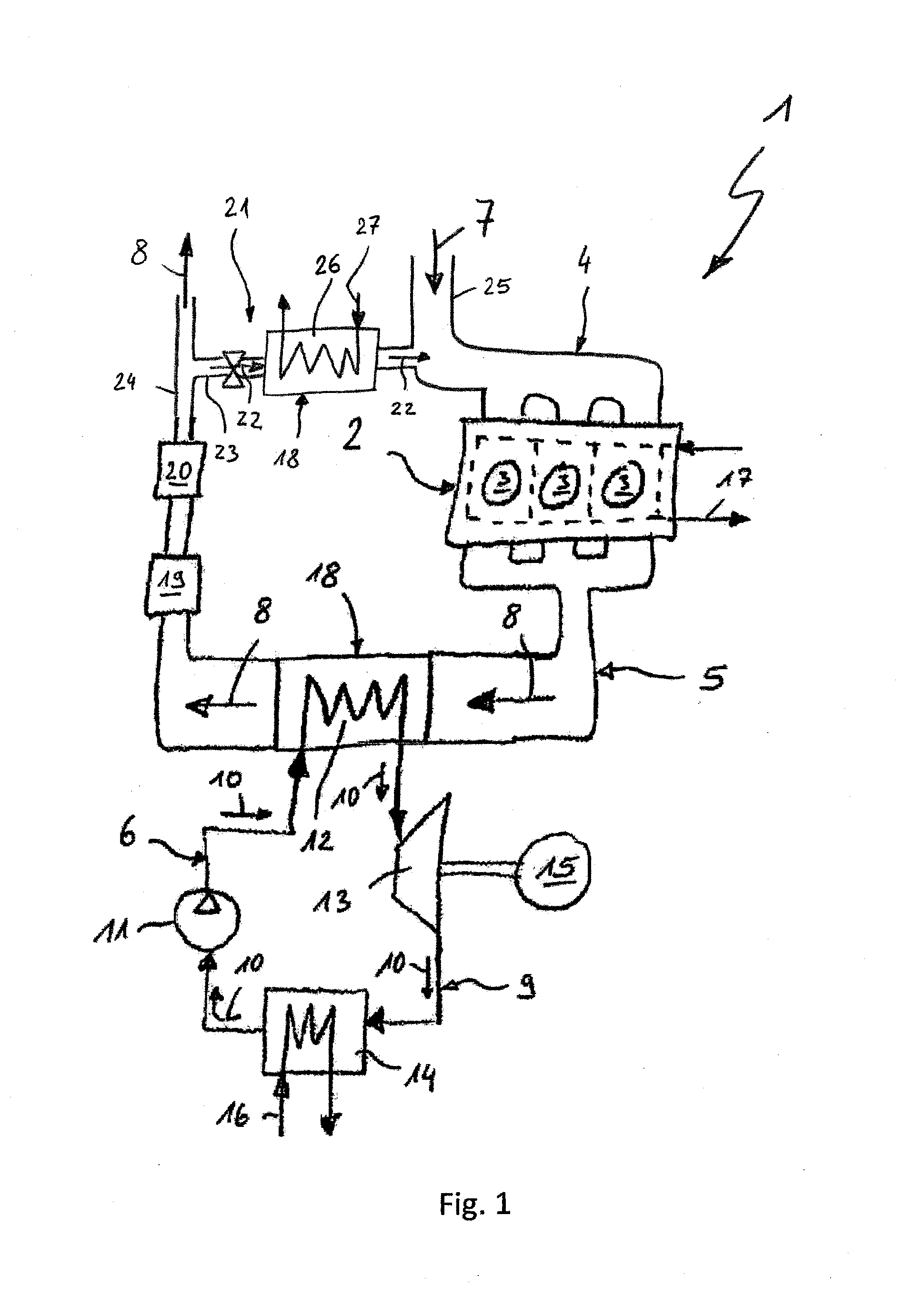
[0030]Referring to the drawings in particular, corresponding to FIG. 1, an internal combustion engine 1 comprises, in the usual manner, an engine block 2 with a plurality of combustion chambers 3, a fresh air feed unit 4 for feeding fresh air to the combustion chambers 3, an exhaust system 5 for removing exhaust gas from the combustion chambers 3 and a waste heat utilization unit 6 for utilizing the heat being carried in the exhaust gas. A fresh air stream 7 being carried in the fresh air feed unit 4 is indicated by an arrow. An exhaust gas stream 8 being carried in the exhaust system 5 is indicated by arrows. The waste heat utilization unit 6 comprises a waste heat utilization circuit 9, in which a working medium circulates, wherein a working medium stream 10 is indicated by arrows. A delivery means 11 for driving the working medium, an evaporator 12 for evaporating the working medium, an expansion engine 13 for expanding the working medium and a condenser 14 for condensing the wor...


PUM


Abstract

A heat exchanger (18) is provided for an internal combustion engine (1) for heat transfer between a gas stream (8) and a working medium stream (10). The heat exchanger (18) comprises a housing (28), which encloses a gas path (38), and with at least one spiral tube (29), which carries a working medium path (30) and which is arranged in the gas path (38) and which extends helically in relation to the central longitudinal axis (31) of the housing (28). Increased fatigue strength is achieved with an elastic outer mounting layer (32). The elastic outer mounting layer (32) is arranged between the housing (28) and the at least one spiral tube (29).

Description

CROSS REFERENCE TO RELATED APPLICATIONS[0001]This application claims the benefit of priority under 35 U.S.C. §119 of German Patent Application DE 10 2013 201 465.1, filed on Jan. 30, 2013, the entire contents of which are incorporated herein by reference.FIELD OF THE INVENTION[0002]The present invention pertains to a heat exchanger for an internal combustion engine for heat transmission between a gas stream and a working medium stream.BACKGROUND OF THE INVENTION[0003]Heat exchangers are used for various applications in internal combustion engines, especially of motor vehicles. For example, a heat exchanger, through which ambient air can flow in order to remove heat from the cooling circuit into the environment, may be integrated into an engine cooling circuit. Furthermore, an interior space air stream can be admitted into a heat exchanger coupled thermally with the engine cooling circuit in order to heat the interior space air stream in this manner. Furthermore, applications are con...

Claims


Application Information

Patent Timeline
Patent Type & Authority Applications(United States)
IPC IPC(8): F01N5/02F28F21/00F28D7/10
CPCF01N5/02F28F21/00F28D7/10F01N3/043F01N3/2853F01N13/16F01N13/1838F01N3/0205F28D7/024F28D21/0003F01N2240/02F01N2240/36F01N2310/02F01N2310/04F01N2310/14F01N2410/03F01N2470/24F28F2235/00F28F2250/06Y02T10/12
Inventor SCHWEIZER, JURGENGAISER, GERDBIRGLER, MARKUSFEUERBACH, MATTHIASKLINGLER, CHRISTOFPENNER, DIMITRIKLEIN, WOLFGANG
Owner EBERSPACHER EXHAUST TECH GMBH & CO
Why Eureka
Try Eureka