
Monolithic ceramic electronic component

Active Publication Date: 2014-07-31
MURATA MFG CO LTD
View PDF3 Cites 8 Cited by
  • Summary
  • Abstract
  • Description
  • Claims
  • Application Information

AI Technical Summary

Benefits of technology

The patent text describes a method of making a monolithic ceramic electronic component that has good moisture resistance and reliability. The method involves using inner electrodes that have regions where they coexist with Magnesium oxide and Nitridum oxide. These Mg—Ni coexistence regions help anchor the inner electrodes to the ceramic layers, reducing the likelihood of delamination and preventing moisture from entering the component. The Mg—Ni coexistence regions have a specific molar ratio and area fraction to provide the strongest anchoring force. This method improves the reliability and performance of monolithic ceramic electronic components.

Problems solved by technology

However, a metal coating formed directly on a certain surface of a body of a component has a problem that the anchoring force between the metal coating and the component body is low because there is no glass or the like therebetween, unlike the electrodes formed by baking the conductive paste as described above.
When the anchoring force therebetween is low, the interface between the metal coating and the component body may possibly be cracked and suffer from the ingress of moisture.
Furthermore, the ingress of moisture into interfaces between ceramic layers and inner electrodes may possibly cause electrical shorts between the inner electrodes, which have different potentials, which impairs functions of the component.

Method used


Image

  • Monolithic ceramic electronic component
  • Monolithic ceramic electronic component
  • Monolithic ceramic electronic component

Examples


example 1

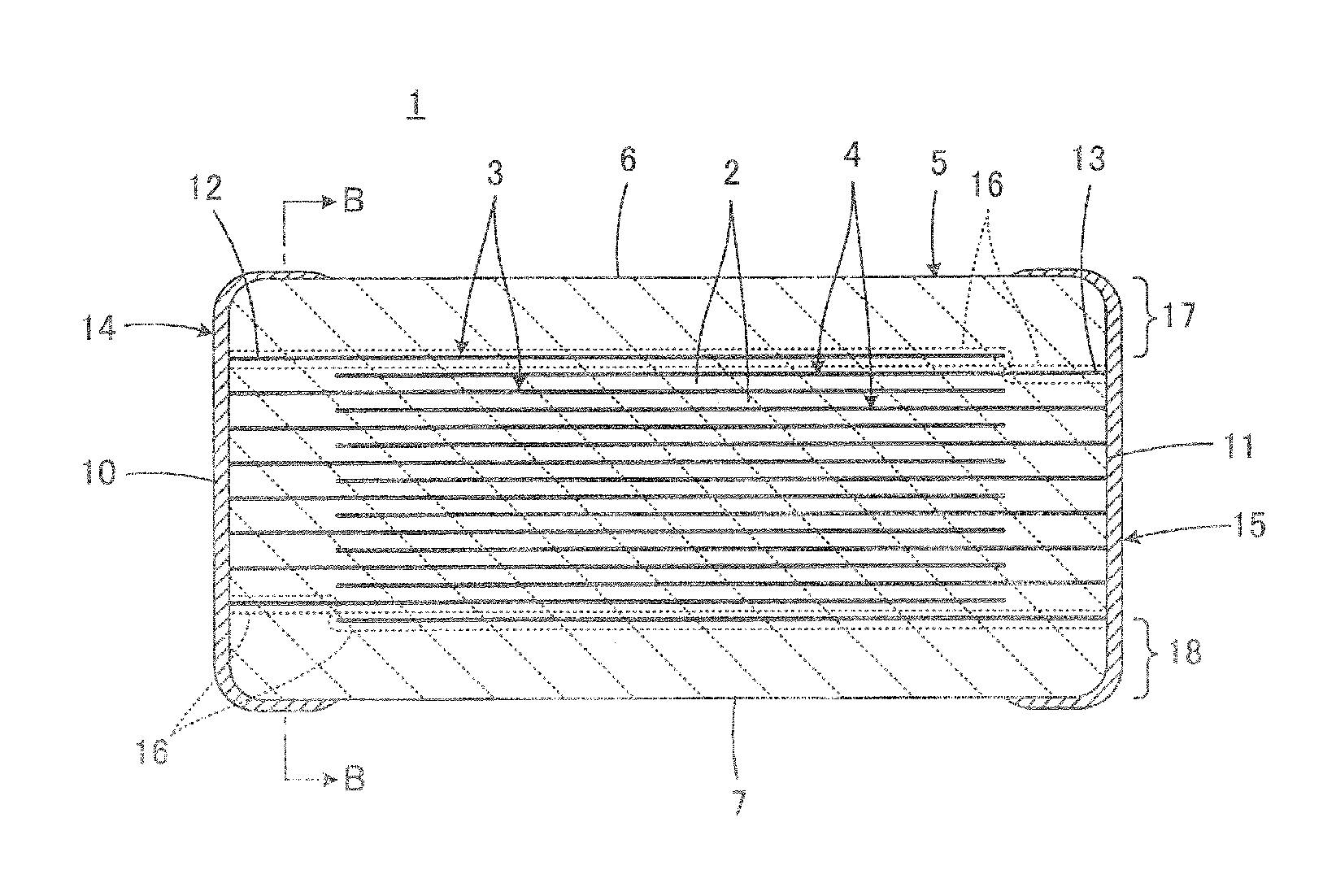
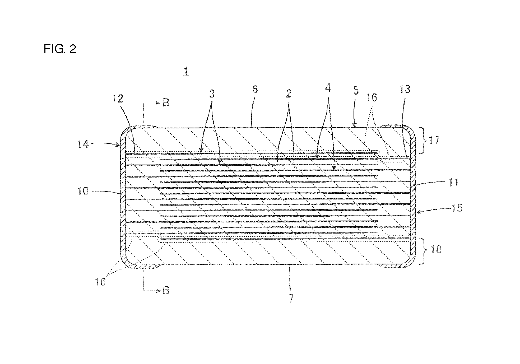
[0047]In Example 1, attention was focused particularly on the Mg—Ni coexistence regions 16 present in the portions of the first and second inner electrodes 3 and 4 that are located in the peripheral section of the region containing the exposed ends 12 and 13 as shown in FIG. 3. Effects of this Mg—Ni coexistence region 16 were investigated.

[0048]Monolithic ceramic electronic components were prepared as samples.

[0049]A component body included in each monolithic ceramic electronic component was obtained as described below. Green ceramic sheets to be formed into ceramic layers and conductive paste films, to be formed into inner electrodes, containing Ni were stacked, such that the green component body was prepared. The green ceramic sheets contained a barium titanate-based dielectric ceramic material containing Mg.

[0050]The green component body was calcined. In the calcination step, the progress of the oxidation of Ni in the conductive paste films was varied in such a way that an oxidiz...

example 2

[0061]In Example 2, attention was focused particularly on the Mg—Ni coexistence regions 16 present in the first and second inner electrodes 3 and 4 that are at an outermost location as shown in FIG. 2 when the region containing the first and second inner electrodes 3 and 4 is viewed in the stacking direction. Effects of these Mg—Ni coexistence regions 16 were investigated.

[0062]Monolithic ceramic electronic components which were not an L-W reverse type and which were different from those prepared in Example 1 were prepared as samples.

[0063]Green component bodies having a composition substantially identical to that of the component bodies used in Example 1 were prepared. Each green component body was calcined. In the calcination step, an oxidizing atmosphere was controlled in the course of heating before green ceramic sheets were sintered, such that the amount of Mg diffusing in inner electrodes was varied and the sintered component body was obtained. The amount of Mg in the inner el...

example 3

[0072]In Example 3, as well as Example 2, attention was focused particularly on the Mg—Ni coexistence regions 16 present in the first and second inner electrodes 3 and 4 that are at an outermost location as shown in FIG. 2 when the region containing the first and second inner electrodes 3 and 4 is viewed in the stacking direction. Effects of these Mg—Ni coexistence regions 16 were investigated.

[0073]Monolithic ceramic electronic components were prepared as samples in substantially the same way as that described in Example 2 except that outer electrodes were formed on each component body in such a way that the component body was subjected to Cu electroplating, Ni electroplating, and then Sn electroplating.

[0074]As shown in Table 3, each region, present in outermost layer, having an Mg-to-Ni molar ratio of about 0.1 or greater and the rate of occurrence of delamination were determined in substantially the same ways as those described in Example 2.

TABLE 3Region, present in outermost la...


PUM

PropertyMeasurementUnit
Fractionaaaaaaaaaa
Fractionaaaaaaaaaa
Fractionaaaaaaaaaa

Abstract

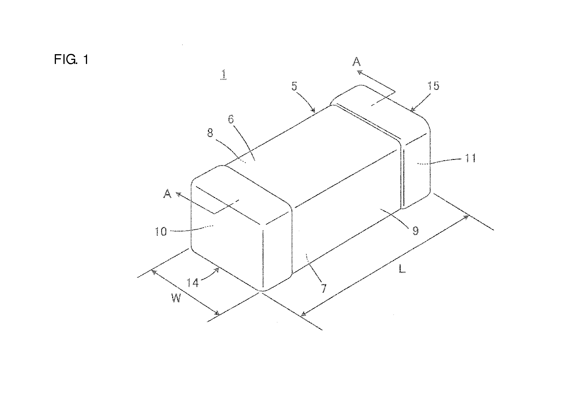
A monolithic ceramic electronic component includes a component body and outer electrodes. The component body includes a plurality of stacked ceramic layers and a plurality of inner electrodes which extend between the ceramic layers, which contain Ni, and which include exposed ends exposed on predetermined surfaces of the component body. The outer electrodes are electrically connected to the exposed ends of the inner electrodes and are formed on the predetermined surfaces of the component body by plating. The inner electrodes include Mg—Ni coexistence regions where Mg and Ni coexist.

Description

BACKGROUND OF THE INVENTION[0001]1. Field of the Invention[0002]The present invention relates to monolithic ceramic electronic components and particularly relates to a monolithic ceramic electronic component including inner electrodes containing Ni and outer electrodes which are electrically connected to the inner electrodes and which are formed by plating.[0003]2. Description of the Related Art[0004]Outer electrodes of a monolithic ceramic capacitor, which is an example of a monolithic ceramic electronic component, are usually formed in such a way that a conductive paste is applied to end portions of a component body and is then baked. However, the thickness of the outer electrodes, which are formed in the above way, is large, about tens to hundreds of micrometers. Therefore, in order to adjust the size of the monolithic ceramic capacitor to a certain standard size, the effective volume for ensuring the electrostatic capacity needs to be undesirably reduced because the volume of th...

Claims


Application Information

Patent Timeline
IPC IPC(8): H01G4/008H01G4/30
CPCH01G4/30H01G4/008H01G4/0085H01G4/12H01G4/232
Inventor SASABAYASHI, TAKEHISAMOTOKI, AKIHIROOGAWA, MAKOTO
Owner MURATA MFG CO LTD
Learn More