Photovoltaic interconnect systems, devices, and methods

a photovoltaic interconnection and photovoltaic technology, applied in the field of photovoltaics, can solve the problems of small electrical imbalance inside the solar cell, overall charge imbalance in the cell, and single conventional solar cell not enough to power most applications

Inactive Publication Date: 2014-07-31
SUN HARMONICS CO LTD
View PDF0 Cites 31 Cited by
  • Summary
  • Abstract
  • Description
  • Claims
  • Application Information

AI Technical Summary

Benefits of technology

[0015]The wire ICI approach according to the present teachings replaces the Cu grid material with Cu wire embedded in a front sheet. Benefits of this new approach include Cu w...

Problems solved by technology

Near the p-n junction between the two materials, valence electrons from the n-type layer move into neighboring holes in the p-type layer, creating a small electrical imbalance inside the solar cell.
This creates an overall charge imbalance in the cell, so that if an external conductive path is provided between the two sides of the cell, electrons will move from the n-type side back to the p-type side along the external path, creating an electric current.
As a standalone device, a single conventional solar cell is not sufficient to power most applications.
However, when comparing technology options applicable during the deposition process, rigid substrates suffer from various shortcomings during processing, such as a need for substantial floor space for processing equipment and material storage, expensive and specialized equipment for heating glass uniformly to elevated temperatures at or near the glass annealing temperature, a high potential for substrate fracture with resultant yield loss, and higher heat capacity with resultant higher electricity cost for heating the glass.
Furthermore, rigid substrates require increased shipping costs due to the weight and fragile nature of the glass.
As a result, the use of glass substrates for the deposition of thin films may not be the best choice for low-cost, large-volume, high-yield, commercial manufacturing of multi-layer functional thin-film materials such as photovoltaics.
Due to the different properties of crystalline substrates and flexible thin film substrates, the electrical series connection between cells may be constructed differently for a thin film cell than for a crystalline cell, and forming reliable series connections between thin film cells poses several challenges.
For example, soldering (the traditional technique used to connect crystalline solar cells) directly on thin film cells exposes the PV coatings of the cells to damaging temperatures, and the organic-based silver inks typ...

Method used


Image

  • Photovoltaic interconnect systems, devices, and methods
  • Photovoltaic interconnect systems, devices, and methods
  • Photovoltaic interconnect systems, devices, and methods

Examples


Embodiment Construction

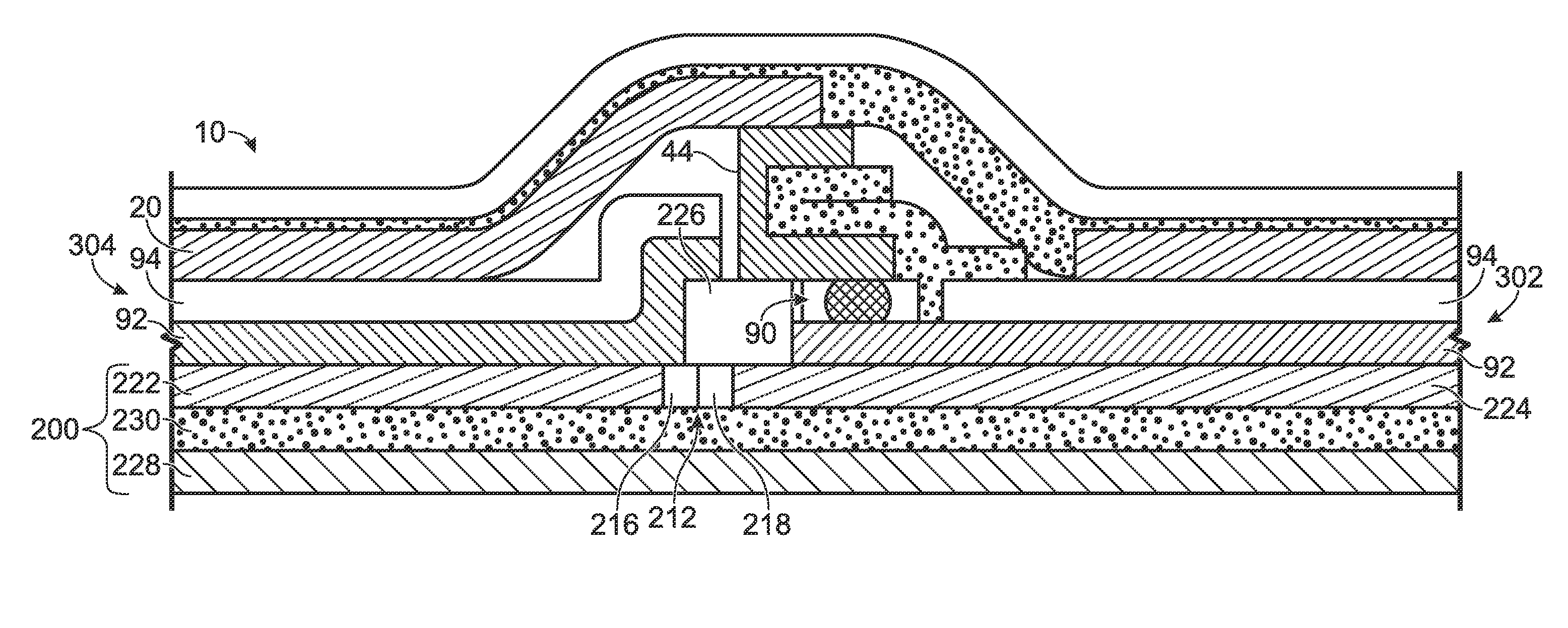
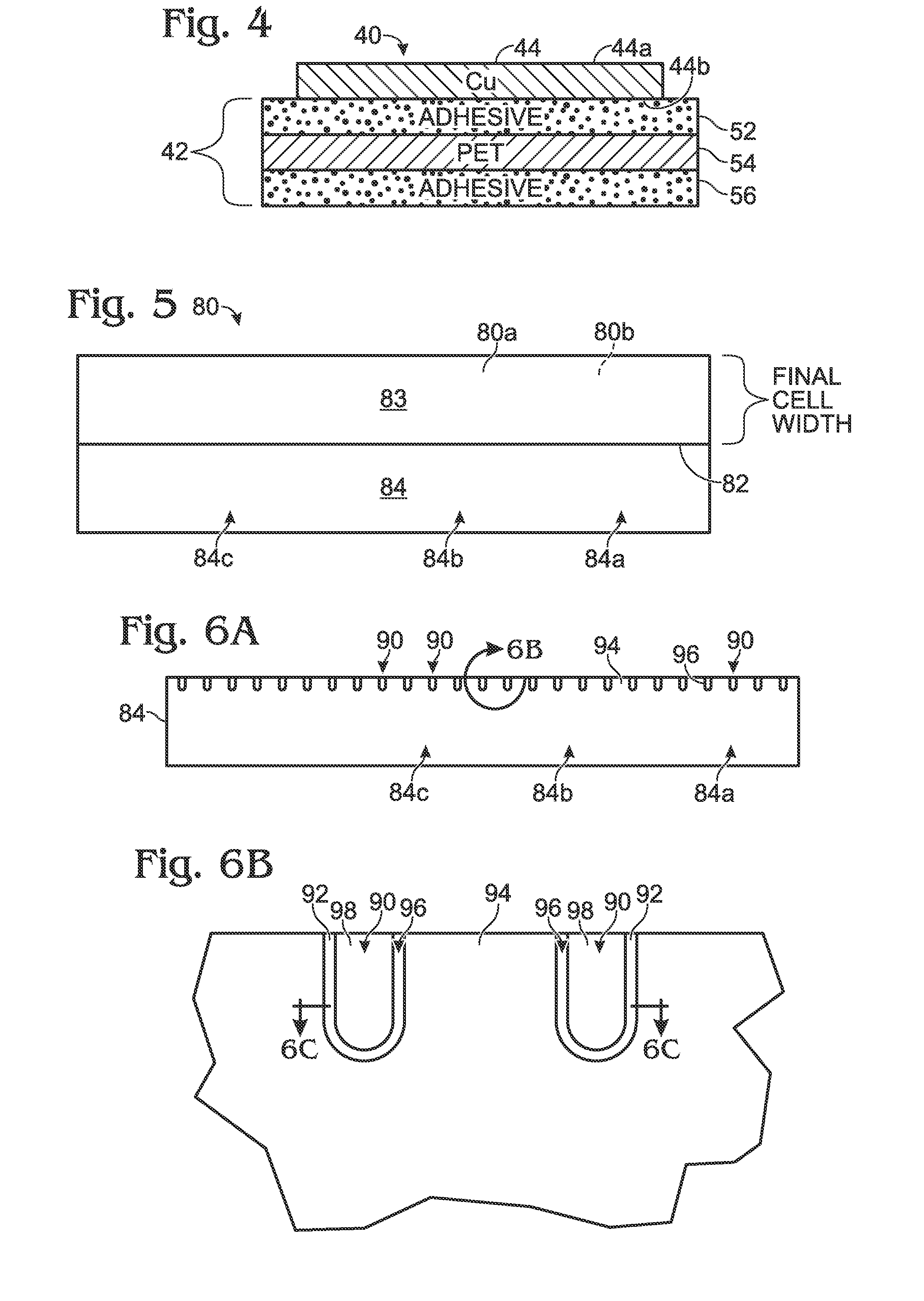
[0050]Systems, devices and methods for interconnecting flexible, thin-film photovoltaic (PV) cells are provided. According to the present teachings, systems and methods of interconnecting thin-film photovoltaic cells may include a series of photovoltaic cells and a transparent top or front sheet covering the cells. Electrically-conductive pathways are established connecting a top or “sunny” side of one cell to the top of the conductive substrate underlying the photoactive material of an adjacent cell. Portions of the photoactive material of the interconnected cells may be scribed away or otherwise removed, to expose the underlying conductive substrate and to facilitate interconnection. The top sheet may include copper wires embedded in a transparent adhesive and configured to form electrical connections between adjacent cells that are placed in contact with the grid.

[0051]FIGS. 1 and 2 depict a substantially optically transparent or transmissive top sheet (or front sheet), generally...


PUM


Abstract

Photovoltaic modules may include multiple flexible thin film photovoltaic cells electrically connected in series by a substantially transparent top sheet having an embedded conductive wire grid pattern. Methods of manufacturing photovoltaic modules including integrated multi-cell interconnections are provided.

Description

CROSS-REFERENCE TO RELATED APPLICATION[0001]This application claims priority from U.S. Provisional Patent Application Ser. No. 61 / 757,636, filed Jan. 28, 2013, which is hereby incorporated herein by reference. This application also incorporates by reference in their entireties the following U.S. patents, U.S. publications, U.S. and foreign applications: U.S. Pat. Nos. 5,681,402, 5,759,291, 4,574,160, 4,617,420, 4,888,061, 4,652,693, 5,391,235, 6,803,513, 5,457,057, 5,181,968, 7,276,724, 5,547,516, 5,735,966, 6,239,352, 6,310,281, 6,372,538, 6,414,235, 6,459,032, 6,690,041, 7,194,197, 7,507,903, 7,635,810, 7,732,243, 7,851,700, 7,868,249, 7,898,053, 7,898,054, 7,989,692, 7,989,063, 8,062,922, 20100147356, 20120000510, 20120000502, 20120006378, 20030121228A1, 20030127128A1, 20040069340, 20050176270, 20060032752, 20060174930, 20060180195, 20080011350, 20080227236, 20080257399, 20080314433, 20090107538, 20090111206, 20090145551, 20090169722, 20090163374, 20090223552, 20090293941, 201001...

Claims


Application Information

Patent Timeline
IPC IPC(8): H01L31/05
CPCH01L31/0504H01L31/0392H01L31/03925H01L31/03928H01L31/046H01L31/0465H01L31/0508H01L31/0512Y02E10/541Y02P70/50H01L31/0488
Inventor BRITT, JEFFREY S.WIEDEMAN, SCOTT
Owner SUN HARMONICS CO LTD
Why Eureka
Try Eureka