Indexing Laminating System

a conveyor system and glass technology, applied in the direction of lamination ancillary operations, chemistry apparatus and processes, glue vessels, etc., can solve the problems of difficulty in heating large glass pieces, prior art glass lamination systems suffer from various deficiencies, and none of these prior art systems provide for glass lamination systems. achieve the effect of promoting water removal

Inactive Publication Date: 2014-08-07
CASSO SOLAR TECH
View PDF4 Cites 14 Cited by
  • Summary
  • Abstract
  • Description
  • Claims
  • Application Information

AI Technical Summary

Benefits of technology

[0010]It is another object of the present invention to provide an infrared heating system where the infrared heaters are arranged to allow for heating zones and can be controlled so that glass laminate is first heated in the center and then outwards towards it edges by controlling the infrared heaters. Having the glass be heated in zones first in the center and then outwards towards it edges allows for air and moisture to the forced radially from the center of the glass laminate to the outer edges of the glass laminate, thus, eliminating air or moisture bubbles in the glass laminate material. This is advantageous as it provides for a glass laminate material that is more uniform and has fewer defects.
[0011]It is a further object of the present invention to provide a glass lamination system using infrared heating for heating large pieces of glass. Large pieces of glass are typically difficult to heat and using zoned heating on large pieces of glass is an effective way to laminate large pieces of glass without producing defects in the glass caused by air or moisture.
[0035]In certain embodiments, the system includes at least one press roll located between each of the modules, where each press roll includes a top roll and a bottom roll. Specifically, at least one press roll can be located between the first module and the second module and / or between the second module and the third module. In certain embodiments, at least one press roll can be located in both locations. In certain embodiments, the at least one press roll helps seal the edges of the laminated material.
[0036]In certain embodiments, the infrared heaters promote the removal of water and moisture from the laminate material.
[0038]In certain embodiments, the second heating module includes doors to close the second heating module. In certain embodiments, the doors keep the heat from exiting the second heating module. In certain embodiments, the laminated material oscillates back and forth in the second heating module. In certain embodiments, the oscillation of the laminated material in the second heating module allows for even heating of the laminated material.
[0040]In certain embodiments, the laminated material oscillates back and forth in the cooling module. In certain embodiments, the cooling module allows for even cooling of the laminated material.

Problems solved by technology

Prior art glass lamination systems suffer from various deficiencies and problems, as these systems typically are not efficient in heating large pieces of glass laminate.
However, such convection systems have difficulty in heating large pieces of glass as large pieces of glass do not typically fit in a convection oven.
However, none of these prior art systems provide for a glass lamination system where the glass laminate is heated via infrared heaters, where the infrared heaters are arranged to allow for heating zones and can be controlled so that the glass is first heated in the center and then outwards towards it edges by controlling the infrared heaters.
None of these prior art systems provide a system having an infrared heater module with controlled heating zones, so that air and moisture are removed from the glass laminate material via heat and vacuum pressure zones.
None of these prior art references solve the problem of using infrared heating for large pieces of glass and glass laminate.

Method used


Image

  • Indexing Laminating System
  • Indexing Laminating System
  • Indexing Laminating System

Examples


Embodiment Construction

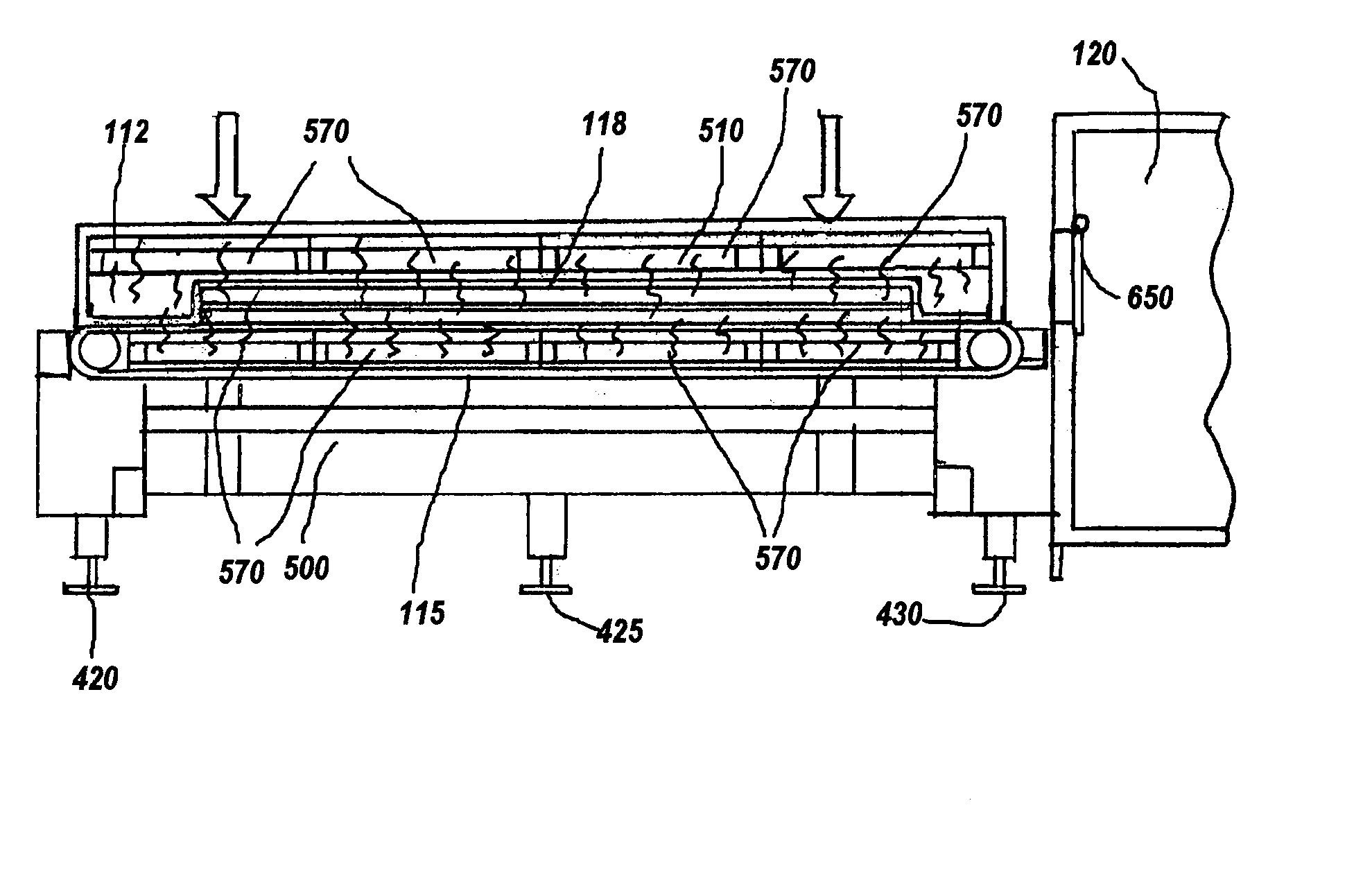
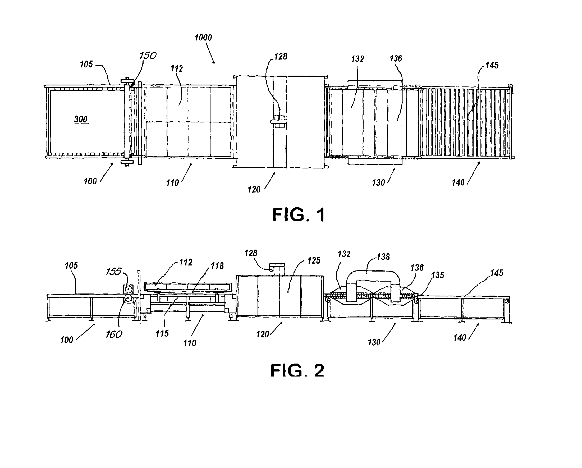
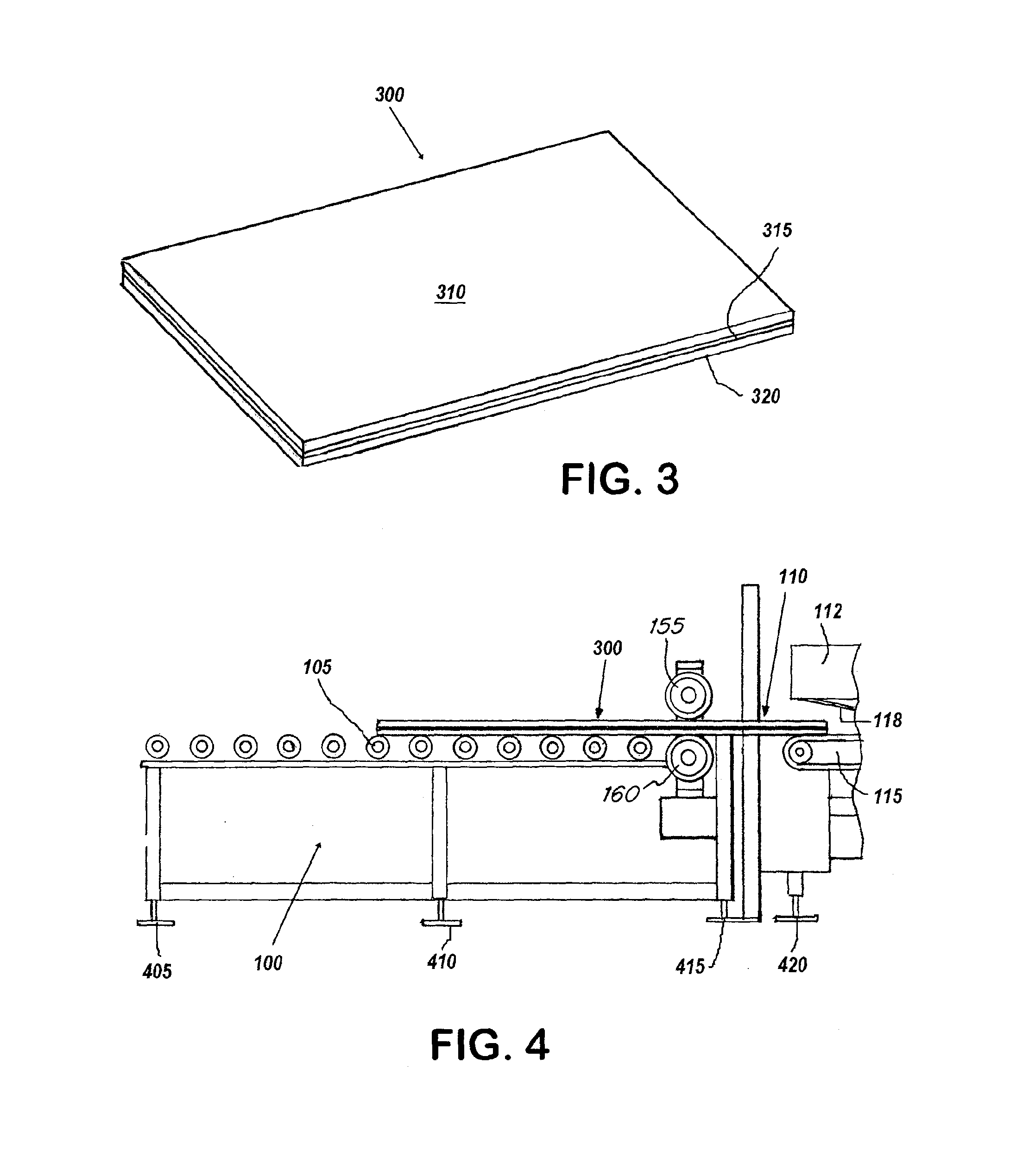
[0073]FIGS. 1 and 2 illustrate a top and side view of a glass lamination system of an embodiment of the invention. FIGS. 1 and 2 show system 1000 having various modules arranged in an assembly for laminating glass.

[0074]FIG. 1 shows module 100, which is where the glass laminate 300 enters the assembly or system 1000. Module 100 has rollers 105, the rollers 105 allowing for the glass laminate 300 to be rolled along the module 100. In certain embodiments, the rollers 105 may be automated or may a conveyor belt instead of rollers 105. Module 100 is an entrance module, where the glass laminate 300 enters the assembly or system 1000.

[0075]In certain embodiments, when a conveyor belt is used, the conveyor belt material is very thin, about 0.010″ thick, so that infrared heating elements may be used. In preferred embodiments, the thickness of the conveyor belt is less than 0.2″ thick. The thinness of the belt allows infrared heat from the infrared heaters to pass through the belt quickly. I...


PUM

PropertyMeasurementUnit
temperatureaaaaaaaaaa
atmospheric pressureaaaaaaaaaa

Abstract

A system for laminating glass having an infrared heating module that includes at least two heating zones for heating a laminated material under vacuum where the two heating zones heat different section of a glass laminate. The system has a convection heating module that includes a heating coil that heats the glass laminate at atmospheric pressure and a cooling module. A system for laminating glass having at least one infrared heating unit, the at least one infrared heating unit arranged to provide three concentric heating zones for heating a laminated material, the three concentric heating zones heating different sections of the laminated material, and operation of the first heating module promotes the removal of air and moisture from the laminating glass.

Description

FIELD OF THE INVENTION[0001]The present invention relates to a system and method for laminating glass using a conveyor system with an assembly that includes infrared heating units.BACKGROUND OF THE INVENTION[0002]Glass lamination systems are known in the art. Prior glass lamination systems include U.S. Pat. No. 7,992,613 Damm et al.; U.S. Pat. No. 7,779,884 Damm et al.; 2010 / 0051195 Damm; 2010 / 0018646 Metzger et al.; 2011 / 0023733 Damm; 2009 / 0294036 Metzger et al.; 2010 / 0288442 Damm; 2008 / 0295956 Damm et al.; 2010 / 0282417 Damm et al.; 2008 / 0053609 Renz; U.S. Pat. No. 8,122,929 Zahnd et al.; 2011 / 0119898 Blanchet et al.; 2012 / 0073746 Zahnd et al.; U.S. Pat. No. 7,624,780 Stevens; U.S. Pat. No. 4,450,033 Little; U.S. Pat. No. 4,421,589 Armini et al.; U.S. Pat. No. 7,726,375 Kasahara et al.; 2009 / 0242137 Ishikawa et al.; U.S. Pat. No. 6,481,482 Shimotomai; U.S. Pat. No. 6,367,530 Shimotomai; U.S. Pat. No. 8,028,735 Chikaki; 2008 / 0041531 Chikaki; U.S. Pat. No. 7,699,085 Chikaki; 2008 / 004...

Claims


Application Information

Patent Timeline
Patent Type & Authority Applications(United States)
IPC IPC(8): B32B37/06
CPCB32B37/06B32B17/10807B32B37/003B32B2310/0825B32B2315/08B32B17/10036B32B17/10871B32B17/10972B32B17/1099
Inventor CANFIELD, DOUGLAS M.
Owner CASSO SOLAR TECH
Why Eureka
Try Eureka