Antenna for a radar detector
a radar detector and antenna technology, applied in the direction of antennas, antenna details, electrically short antennas, etc., can solve the problems of increasing the size of the radar detector, increasing the number of power supply units required for each antenna, and complicated circuits, etc., to achieve simplified circuit configuration, high gain, and large bandwidth
- Summary
- Abstract
- Description
- Claims
- Application Information
AI Technical Summary
Benefits of technology
Problems solved by technology
Method used
Image

Examples
first embodiment
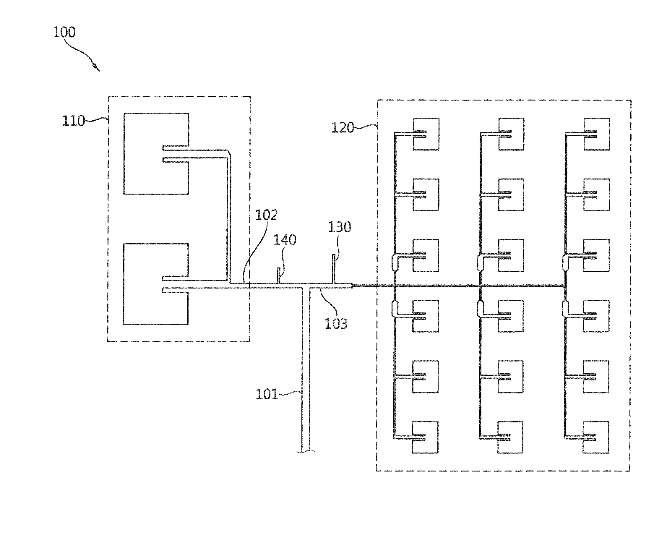
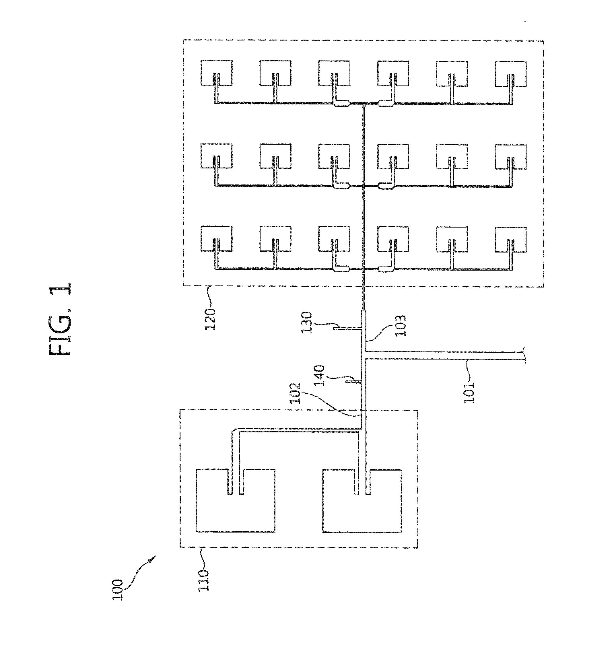
[0028]FIG. 1 is a plan view illustrating an antenna for a radar detector according to the present invention.
[0029]As illustrated in FIG. 1, an antenna for a radar detector 100 according to a first embodiment of the present invention includes a power supply unit 101 to which a detecting target signal is applied, a first branch 102 and a second branch 103 branched from the power supply unit 101, a first band patch antenna 110 connected to the first branch 102, and a second band patch antenna 120 connected to the second branch 103, a second band stub placed on the first branch, and a first band stub 130 placed on the second branch.
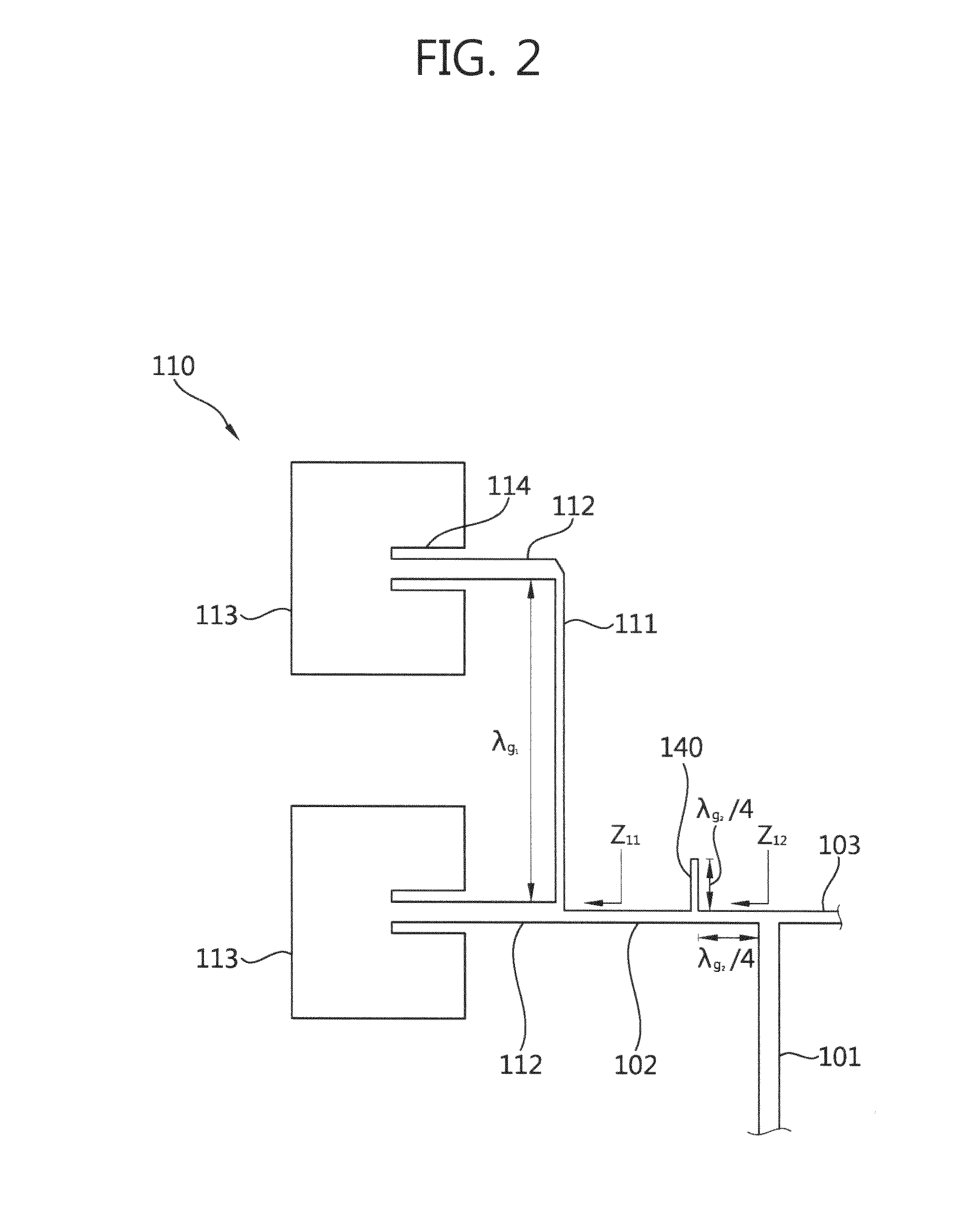
[0030]FIG. 2 is a diagram illustrating a first band patch antenna of the antenna for the radar detector according to the first embodiment of the present invention. The patch antenna may be formed on a dielectric substrate (not illustrated) having a predetermined thickness, and may be formed on the substrate by using a metal foil such as copper (Cu) or aluminu...
second embodiment
[0079]FIG. 8 is a plan view illustrating an antenna for a radar detector according to the present invention.
[0080]As illustrated in FIG. 8, an antenna for a radar detector 200 according to the second embodiment of the present invention may further include a third band patch antenna 130 which may selectively operate with respect to three band areas.
[0081]The antenna for the radar detector 200 according to the second embodiment of the present invention includes a power supply unit 101, a first branch 102, a second branch 103, and a third branch 104 branched from the power supply unit 101, a first band patch antenna 110 connected to the first branch 102, a second band patch antenna 120 connected to the second branch 103, and a third band patch antenna 130 connected to the third branch 103, a second band first stub 141 and a third band first stub 151 disposed on the first branch, a first band first stub 131 and a third band second stub 152 disposed on the second branch, and a first band...
third embodiment
[0104]FIG. 9 is a plan view illustrating an antenna for a radar detector according to the present invention.
[0105]When comparing an antenna for a radar detector 300 according to a third embodiment of the present invention with the antenna for the radar detector 100 according to the first embodiment, a first band patch antenna 310 and a second band patch antenna 320 include a plurality of radiation patches 313a, 313b, 323a, 323b, and 323c with insets 314a, 314b, 324a, 324b, and 324c having difference lengths.
[0106]As illustrated in FIG. 9, the first band patch antenna 310 of the antenna for the radar detector 300 according to the third embodiment of the present invention may include a first band first radiation patch 313a and a first band second radiation patch 313b having different lengths of the insets 314a and 314b.
[0107]Further, the second band patch antenna 320 may include at least one radiation module 320a including a second band first radiation patch 323a, a second band secon...
PUM
 Abstract
Description
Claims
Application Information
 - R&D Engineer
- R&D Manager
- IP Professional
- Industry Leading Data Capabilities
- Powerful AI technology
- Patent DNA Extraction
Browse by: Latest US Patents, China's latest patents, Technical Efficacy Thesaurus, Application Domain, Technology Topic.
© 2024 PatSnap. All rights reserved.Legal|Privacy policy|Modern Slavery Act Transparency Statement|Sitemap