Inspection Device and Inspection Method
a technology of inspection device and inspection method, which is applied in the direction of magnetic field measurement using magneto-optic devices, instruments, material magnetic variables, etc., can solve the problem of sensor unit thickness and noise, and achieve the effect of improving the sensitivity of the magnetic field
- Summary
- Abstract
- Description
- Claims
- Application Information
AI Technical Summary
Benefits of technology
Problems solved by technology
Method used
Image

Examples
first embodiment
[0033]In the following, an inspection device and an inspection method in accordance with a first embodiment of the present invention will be described referring to FIGS. 1-12.
[0034]First, the overall configuration of the inspection device according to this embodiment will be explained referring to FIGS. 1-3.
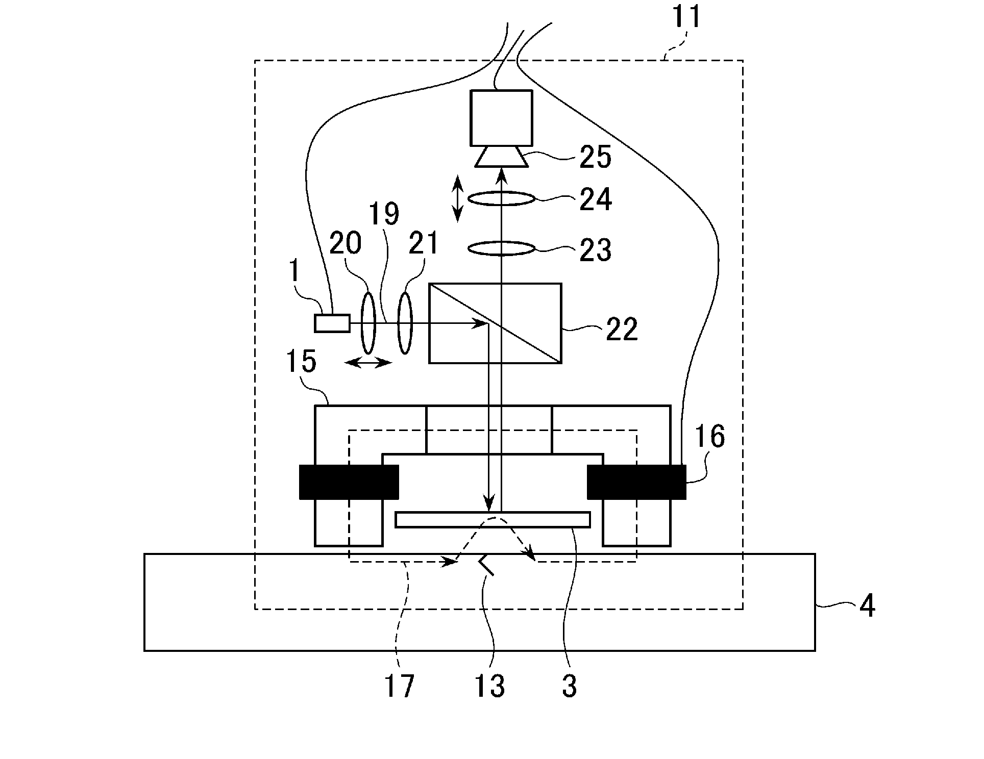
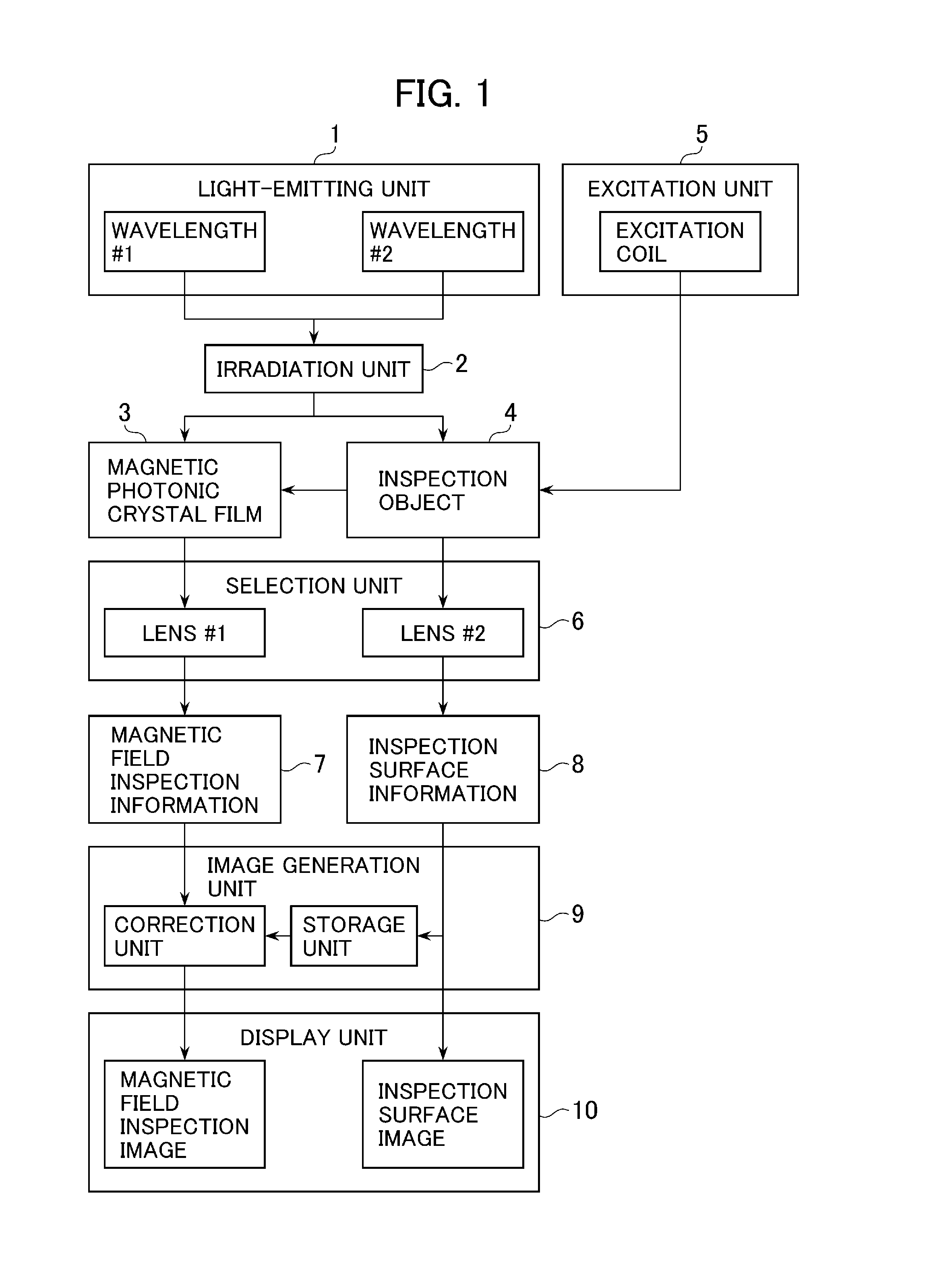
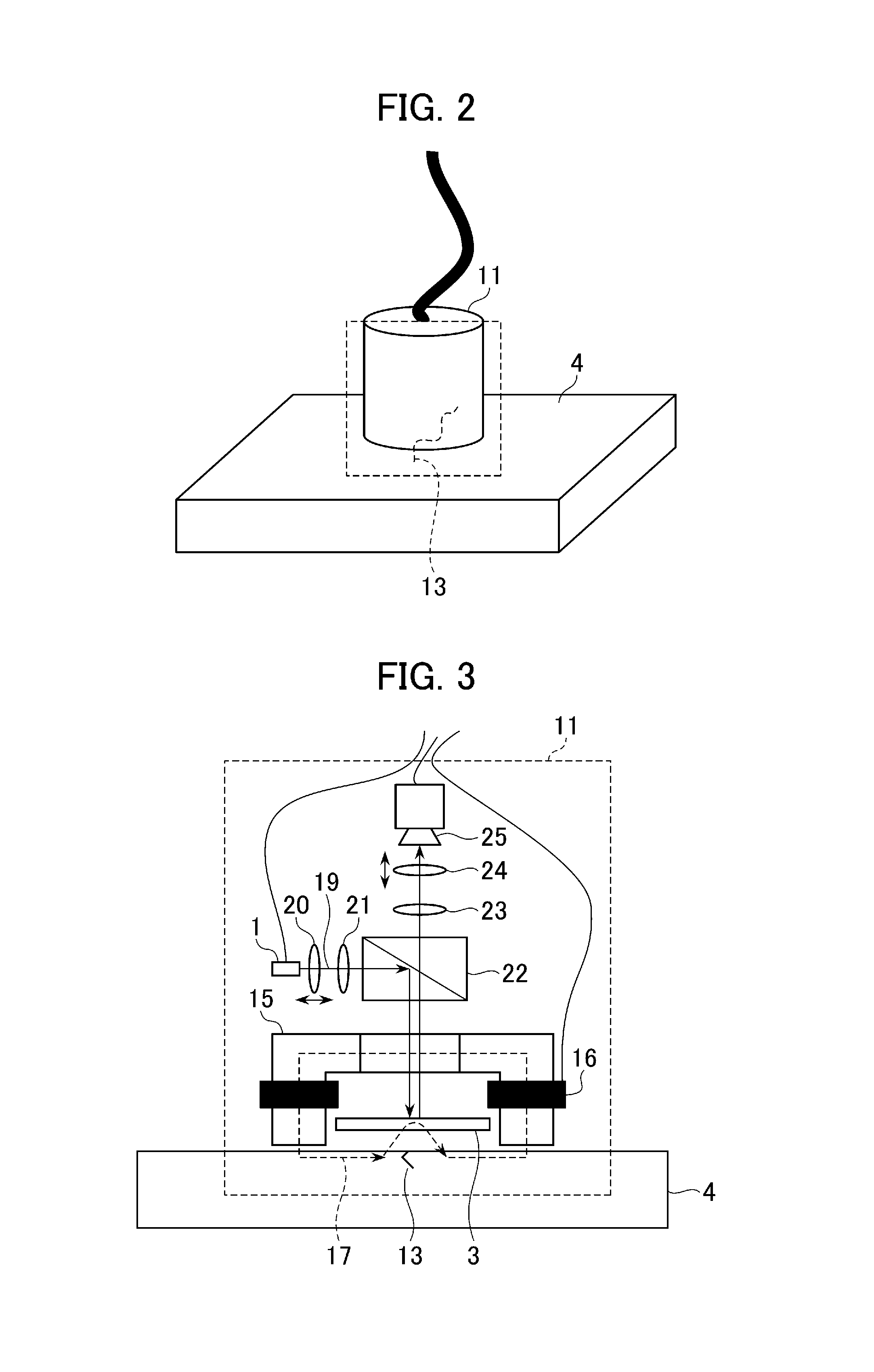
[0035]FIG. 1 is a block diagram showing the overall configuration of the inspection device according to the first embodiment of the present invention. FIG. 2 is a schematic diagram for explaining a crack measurement scheme employed by the inspection device according to the first embodiment of the present invention. FIG. 3 is a detailed configuration diagram of a principal part of the inspection device according to the first embodiment of the present invention. In FIGS. 1-3, identical reference characters represent the same component. Incidentally, the example shown in FIGS. 2 and 3 is not intended to restrict this embodiment of the present invention.
[0036]In the magnetic field in...
second embodiment
[0092]Next, an inspection device and an inspection method in accordance with a second embodiment of the present invention will be described below referring to FIG. 13. FIG. 13 is a block diagram showing the overall configuration of the inspection device according to the second embodiment of the present invention. In FIG. 13, reference characters identical with those in FIG. 1 represent components identical with those in FIG. 1.
[0093]While the inspection device of this embodiment has substantially the same configuration as the device of FIG. 1, an autofocus lens 101 is employed in this embodiment for the following reason: Since the distance between the photoreceptor device 25 (e.g., camera) and the focal point is changed for the acquisition of the magnetic field inspection image and the optical inspection image, it has been necessary to adjust the lens or to prepare multiple lenses suitable for the different focal lengths. By employing the autofocus lens 101 for the lens unit of the ...
third embodiment
[0099]Next, the configuration and operation of an inspection device in accordance with a third embodiment of the present invention will be described below referring to FIGS. 14A-16C.
[0100]FIGS. 14A-16C illustrate an embodiment in which an optical system employing an optical fiber is used.
[0101]FIGS. 14A and 14B show an example of a measurement scheme of the inspection device employing an optical fiber. As shown in FIG. 14A, a sensor unit of the probe 201 is connected to an inspection device main unit 301 (main unit of the inspection device) via a cable 202 formed of an optical fiber. A monitor 401 for displaying measurement images and input devices to be used for inputting probe control information and for operating the measurement images (e.g., a keyboard 402 and a pointing device 403) are connected to the inspection device main unit 301. This configuration allows the inspector to observe the inspection data acquired according to the present invention.
[0102]Since the optical system...
PUM
| Property | Measurement | Unit |
|---|---|---|
| wavelength | aaaaa | aaaaa |
| wavelength | aaaaa | aaaaa |
| reflectivity | aaaaa | aaaaa |
Abstract
Description
Claims
Application Information
 - R&D
- Intellectual Property
- Life Sciences
- Materials
- Tech Scout
- Unparalleled Data Quality
- Higher Quality Content
- 60% Fewer Hallucinations
Browse by: Latest US Patents, China's latest patents, Technical Efficacy Thesaurus, Application Domain, Technology Topic, Popular Technical Reports.
© 2025 PatSnap. All rights reserved.Legal|Privacy policy|Modern Slavery Act Transparency Statement|Sitemap|About US| Contact US: help@patsnap.com