
Material for organic electroluminescent elements, and organic electroluminescent element using the same

Inactive Publication Date: 2014-08-21
IDEMITSU KOSAN CO LTD
View PDF6 Cites 7 Cited by
  • Summary
  • Abstract
  • Description
  • Claims
  • Application Information

AI Technical Summary

Benefits of technology

The inventors conducted extensive research and found that using a compound with a high triplet energy and good carrier-transporting properties can improve the performance of organic EL devices. The invention provides a compound with these properties and a material for an organic EL device containing it. This can lead to better quality and more efficient organic EL devices.

Problems solved by technology

It is known that a highly efficient phosphorescent organic EL device cannot be obtained by merely applying fluorescent device technology due to the emission characteristics.
Therefore, in a phosphorescent organic EL device, such a hydrocarbon-based compound is hardly selected.
As a result, an organic compound including a hetero atom such as oxygen and nitrogen is selected, and hence a phosphorescent organic EL device has a problem that it has a short lifetime as compared with a fluorescent organic EL device.
If a structure, in which the π conjugation is cut, is taken in order to increase the triplet energy of the compound, transporting properties of carriers may be deteriorated.
However, if the π conjugation is elongated, a problem then arises that the triplet energy is lowered.

Method used


Image

  • Material for organic electroluminescent elements, and organic electroluminescent element using the same
  • Material for organic electroluminescent elements, and organic electroluminescent element using the same
  • Material for organic electroluminescent elements, and organic electroluminescent element using the same

Examples


synthesis example 1

Synthesis of Compound (1)

Synthesis of Compound (1-a)

[0156]

[0157]84.10 g (500 mmol) of dibenzofuran and 500 ml of dichloromethane were placed in a three-neck flask to allow the dibenzofuran to be dissolved in the dichloromethane. The resulting solution was cooled to 0° C. in ice water. Then, a solution of bromine 52.5 ml (1025 mmol) / dichloromethane 200 ml was added dropwise over 30 minutes. Then, the resulting mixture was stirred at 0° C. for 2 hours, and subsequently, was allowed to stand at room temperature. The reaction was completed after stirring for 3 days. After completion of the reaction, an aqueous solution of sodium thiosulfate / sodium hydroxide was added to allow the remaining bromine to be deactivated. The resultant was transferred to a separating funnel, a dichloromethane phase was recovered, and extraction was conducted several times from an aqueous phase with dichloromethane. The solution was dried with anhydrous magnesium sulfate, filtered, and concentrated and evapora...

synthesis example 2

Synthesis of Compound (59)

[0167]

[0168]In a nitrogen atmosphere, 15.3 g (40.6 mmol) of compound (1-c), 4.00 ml (16.9 mmol) of 2,3-dibromopyridine, 60 ml of potassium carbonate 2M aqueous solution, 160 ml of toluene and 60 ml of ethanol were placed in a three-neck flask. To the mixed solution, 0.976 g (0.845 mmol) of tetrakis(triphenylphosphine)palladium was added, and refluxed for 16 hours.

[0169]After completion of the reaction, the resultant was cooled to room temperature, and extraction was conducted with dichloromethane by means of a separating funnel. The solution was dried with anhydrous magnesium sulfate, filtered, and concentrated. The filtrate was purified by passing through a short column of silica gel (eluent dichloromethane-dichloromethane:ethyl acetate=4:1) to obtain compound (59). The yield was 4.50 g (36%).

synthesis example 3

Synthesis of Compound (60)

[0170]

[0171]In a nitrogen atmosphere, 7.56 g (20.0 mmol) of compound (1-c), 2.00 g (8.35 mmol) of 4-chloro-3-iodopyridine, 30 ml of potassium carbonate 2M aqueous solution, 80 ml of toluene and 30 ml of ethanol were placed in a three-neck flask. To the mixed solution, 0.482 g (0.418 mmol) of tetrakis(triphenylphosphine)palladium was added, and refluxed for 16 hours.

[0172]After completion of the reaction, the resultant was cooled to room temperature, and extraction was conducted with dichloromethane by means of a separating funnel. The solution was dried with anhydrous magnesium sulfate, filtered, and concentrated. The filtrate was purified by passing through a short column of silica gel (eluent dichloromethane-dichloromethane:ethyl acetate=4:1) to obtain compound (60). The yield was 3.38 g (55%).


PUM


Abstract

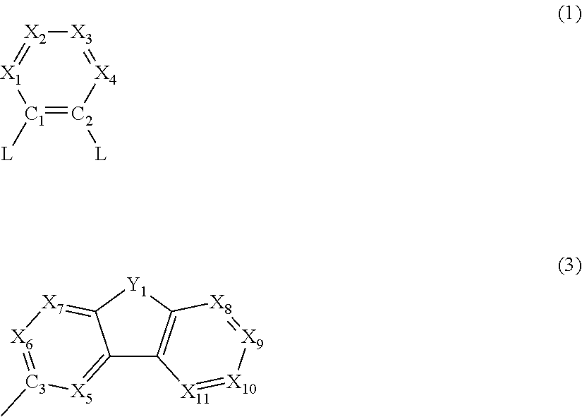
A compound represented by the following formula (1):wherein C1 and C2 are independently a carbon atom; X1 to X4 are independently N, CH or C(R1); L is a group represented by the formula (2): -L1-(A)n; L1 is a group represented by the formula (3); A is alkyl, cycloalkyl, alkoxy, cycloalkoxy, aryl, aryloxy, arylthio, heteroaryl, heteroaryloxy, amino, silyl, diaryloxyphosphinyl, a divalent group corresponding to these groups, fluoro or cyano.

Description

TECHNICAL FIELD[0001]The invention relates to a material for an organic electroluminescence device and an organic electroluminescence device.BACKGROUND ART[0002]An organic electroluminescence (EL) device includes a fluorescent organic EL device or a phosphorescent organic EL device, and a device design optimum for the emission mechanism of each type of organic EL device has been studied. It is known that a highly efficient phosphorescent organic EL device cannot be obtained by merely applying fluorescent device technology due to the emission characteristics. The reasons therefor are generally considered to be as follows.[0003]Specifically, since phosphorescence utilizes triplet excitons, a compound used for forming an emitting layer must have a large energy gap. This is because the energy gap (hereinafter often referred to as “singlet energy”) of a compound is normally larger than the triplet energy (in the invention, the difference in energy between the lowest excited triplet state...

Claims


Application Information

Patent Timeline
IPC IPC(8): H01L51/00
CPCH01L51/0067H01L51/0073H01L51/0072C07D209/86C07D307/91C07D401/14C07D405/14C07D409/14C07D413/14C07D417/14C07D491/048C07D519/00C07F7/0812C07F9/65586H10K85/653H10K85/655H10K85/654H10K85/6576H10K85/6574H10K85/6572H10K85/657H10K85/40H10K50/11H10K2101/10H10K50/15H10K50/16H10K50/171C09K11/06C07D235/18C09K2211/1044C09K2211/185
Inventor SHIOMI, TAKUSHIHASHIMOTO, RYOHEINAGASHIMA, HIDEAKI
Owner IDEMITSU KOSAN CO LTD
Learn More