
Powder and granular material separation processing device, powder and granular material separation processing method, and powder and granular material separation and collection processing system

a technology of granular material and processing device, which is applied in the direction of solid separation, gas current separation, sorting, etc., can solve the problems of complex distribution of grain sizes, and achieve the effects of efficient separation, high versatility, and reduced load of external suction machine connection

Active Publication Date: 2014-08-28
KASHIWABARA
View PDF8 Cites 3 Cited by
  • Summary
  • Abstract
  • Description
  • Claims
  • Application Information

AI Technical Summary

Benefits of technology

The present invention relates to a device and method for separating powder and granular materials, such as abrasocaust and industrial waste powder, from a mixture for recycling and reuse. The device can efficiently separate the recyclable materials from the industrial waste powder and collect them inside a system, reducing the load on external suction machines. The device is portable and can be easily installed on-site. The method involves guiding the mixture through multiple stages of separation using a combination of cascade falling and suction discharge. The device and method are flexible and versatile, capable of separating various mixtures containing powder and granular materials. Overall, the invention promotes material recycling and reduces waste.

Problems solved by technology

However, since the crushed waste plastics are required (allowed) to have a grain diameter of 10 mm or less, it is presumed that the distribution of the grain sizes is complex and bulk specific gravity is different.

Method used


Image

  • Powder and granular material separation processing device, powder and granular material separation processing method, and powder and granular material separation and collection processing system
  • Powder and granular material separation processing device, powder and granular material separation processing method, and powder and granular material separation and collection processing system
  • Powder and granular material separation processing device, powder and granular material separation processing method, and powder and granular material separation and collection processing system

Examples


first embodiment

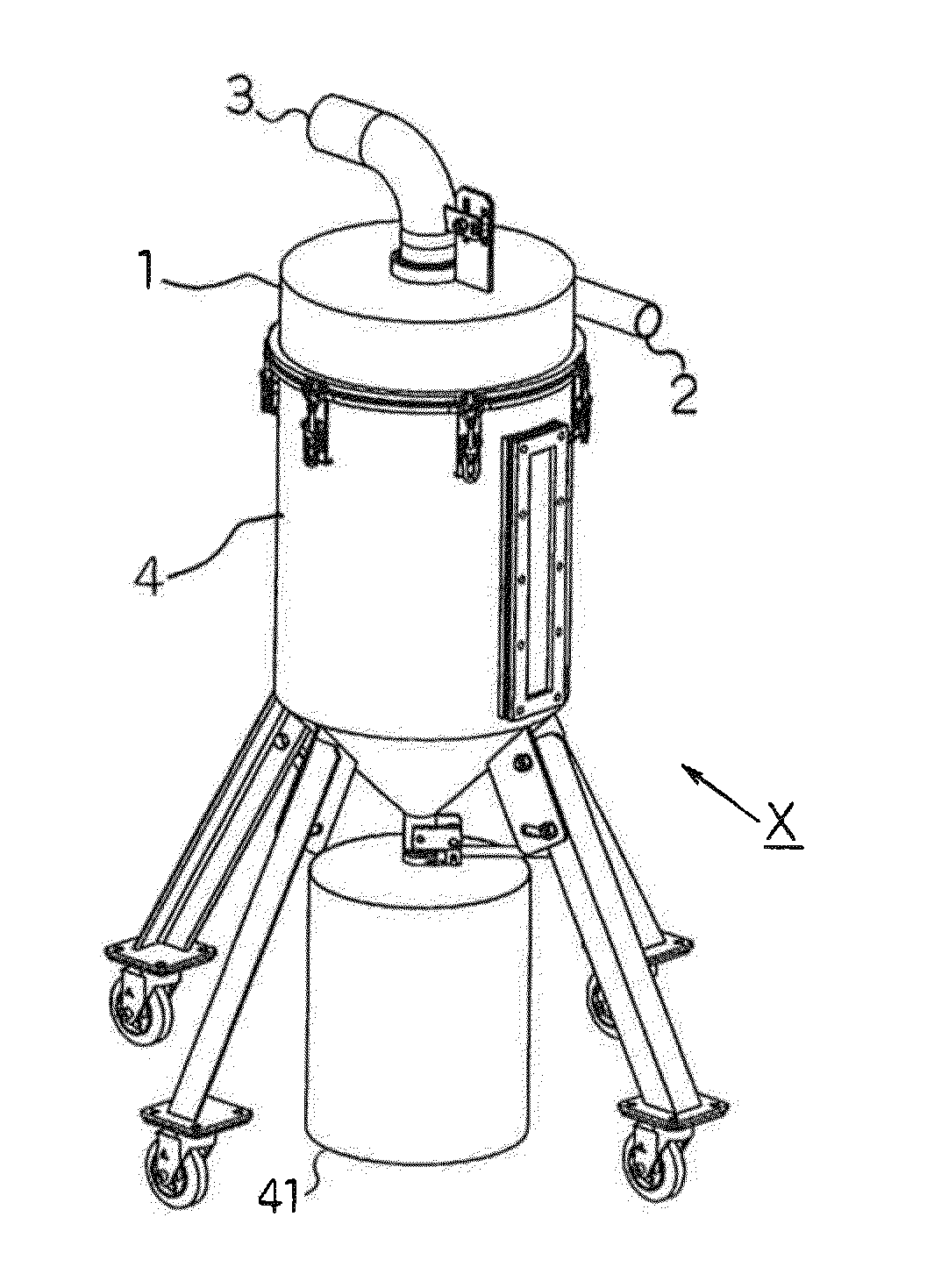
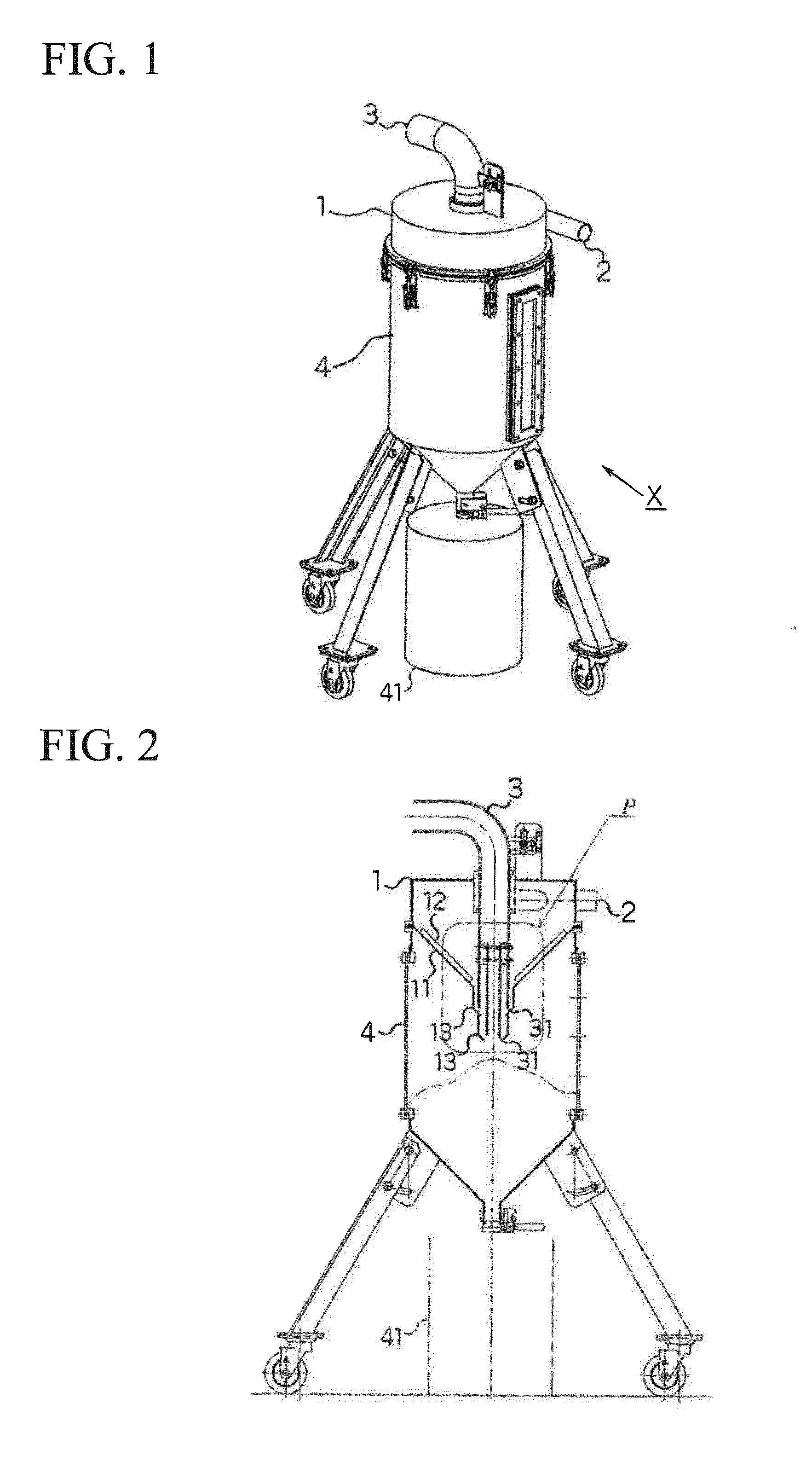
[0074]A description will be given, with reference to the accompanying drawings, of an embodiment of the powder and granular material separation processing device (hereinafter referred to as the embodiment device X) of the present invention according to the first basic application.

[0075]FIG. 1 illustrates a perspective explanatory diagram of the embodiment device X.

[0076]As illustrated in the figure, the embodiment device X is connected to an external suction machine (omitted in the figure) such as a dust collection device and an electric vacuum cleaner, introduces by suction a mixture to be processed, in which powder and granular material made of a system abrasive subjected to a blast process by a dry air blast device (omitted in the figure) and accompanying light weight foreign substances are mixed together, into a separation processing container 1, separates the same with the application of an air flow and a specific gravity difference by a dry method, and discharges the lightweig...

second embodiment

[0112]A description will be given, with reference to the accompanying drawings, of the powder and granular material separation and collection processing system (hereinafter referred to as an embodiment system Z) as an embodiment of the present invention according to the second basic application.

[0113]FIG. 7 illustrates a configuration outline explanatory diagram in a front view, FIG. 8 illustrates a configuration outline explanatory diagram in a plan view, and FIG. 9 is a configuration outline explanatory diagram taken along the line indicated by arrows I-I in FIG. 7.

[0114]In addition, FIG. 10 illustrates a configuration outline explanatory diagram of the embodiment system Z illustrating an example of connecting to an operation site.

[0115]As illustrated in the figures, the embodiment system Z includes a powder and granular material separation processing device X (see FIG. 11 described later) that introduces by suction a mixture to be processed, in which powder and granular material ...


PUM


Abstract

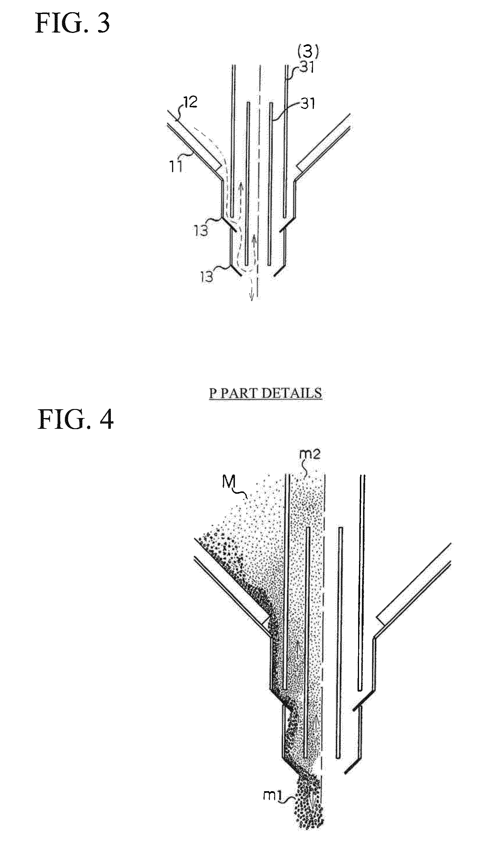
To introduce a mixture to be processed, in which powder and granular material with relatively large specific gravity and hardness and accompanying lightweight foreign substances are mixed together, inside a system and separate the same by a dry method.Disclosed is a powder and granular material separation processing device X that is connected to an external suction machine such as a dust collection device and an electric vacuum cleaner, introduces by suction a mixture to be processed into a separation processing container 1, and discharges lightweight foreign substances to the outside of a system while collecting powder and granular material inside the system. The separation processing container 1 has a suction introduction tube 2 that is attached and sealed as the upper part structure of a hopper tank 4 that collects and stores the powder and granular material and receives the mixture to be processed on the circumferential surface thereof, and a suction discharge tube 3 that is connected to an external suction machine on the upper surf a thereof. In addition, the separation processing container 1 has a separation cone 11 with a funnel-shaped bottom surface and a cylindrical opening 13 that hangs in a protruding shape downward from the tip part of the separation cone 11 and of which the opening diameter thereof is reduced stepwise to have multiple steps. The suction discharge tube 3 has a multiple tube configuration at the tip part thereof in which each tube is given a small diameter corresponding to each opening diameter of the cylindrical opening 13 to be loosely inserted and face the tip part of an opening.

Description

TECHNICAL FIELD[0001]The present invention relates to a powder and granular material separation processing device, a powder and granular material separation processing method, and a powder and granular material separation and collection processing system that introduce by suction a mixture to be processed, in which powder and granular material with relatively large specific gravity and hardness and initially formed into a grit or shot shape with a grain diameter of several mm or less and accompanying lightweight foreign substances are mixed together, inside a system and separate the powder and granular material from the lightweight foreign substances by a dry method.[0002]More specifically, the present invention according to the first basic application (JP 2011-213978 A) relates to the powder and granular material separation processing device and the powder and granular material separation processing method that are used to introduce by suction the mixture to be processed into a sep...

Claims


Application Information

Patent Timeline
IPC IPC(8): B07B4/02
CPCB07B4/02B07B7/01B07B7/04B07B4/04
Inventor TOKUDA, TOMOAKIYAMAMOTO, SHUJI
Owner KASHIWABARA
Learn More