Functional based repair of superalloy components

a superalloy and functional technology, applied in the field of materials technologies, can solve the problems of difficult welding, limited application of micro-cladding, and limited application of these processes to horizontal surfaces

Active Publication Date: 2014-09-04
SIEMENS ENERGY INC
View PDF14 Cites 13 Cited by
  • Summary
  • Abstract
  • Description
  • Claims
  • Application Information

AI Technical Summary

Problems solved by technology

The application of these processes is also limited to horizontal surfaces due to the requirement of pre-placing the powder
Laser microcladding is limited by its low deposition rate, such as on the order of 1 to 6 cm3 / hr Furthermore, because the protective argon shield tends to dissipate before the clad material is fully cooled, superficial oxidation and nitridation may occur on the surface of the deposit, which is problematic when multiple layers of clad material are necessary to achieve a desired cladding thickness.
Alloys outside the zone of weldability are recognized as being very difficult to weld with traditional processes, and the alloys with the highest aluminum content are generally found to be the most difficult to weld, as indicated by the arrow

Method used


Image

  • Functional based repair of superalloy components
  • Functional based repair of superalloy components
  • Functional based repair of superalloy components

Examples


Embodiment Construction

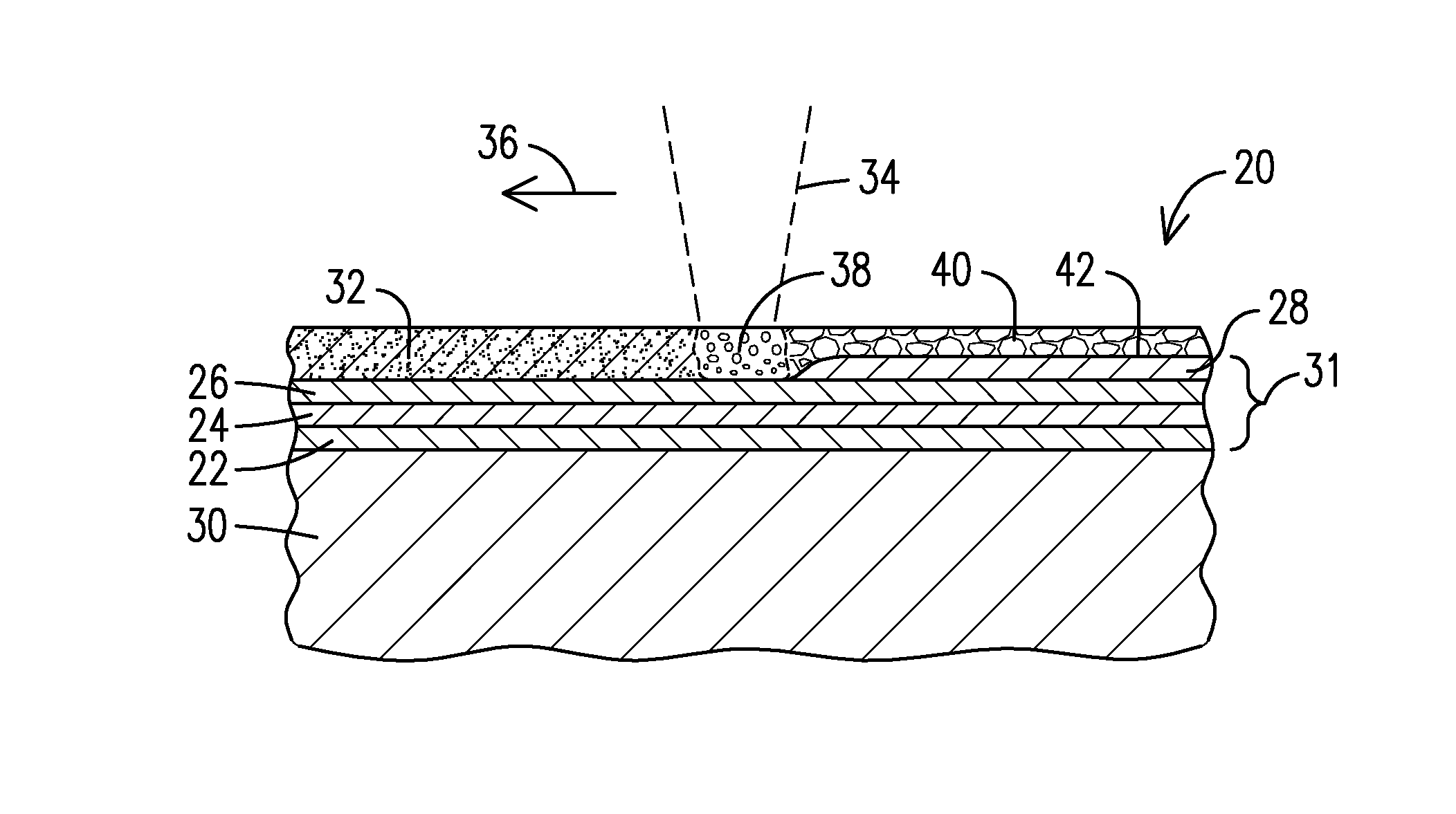
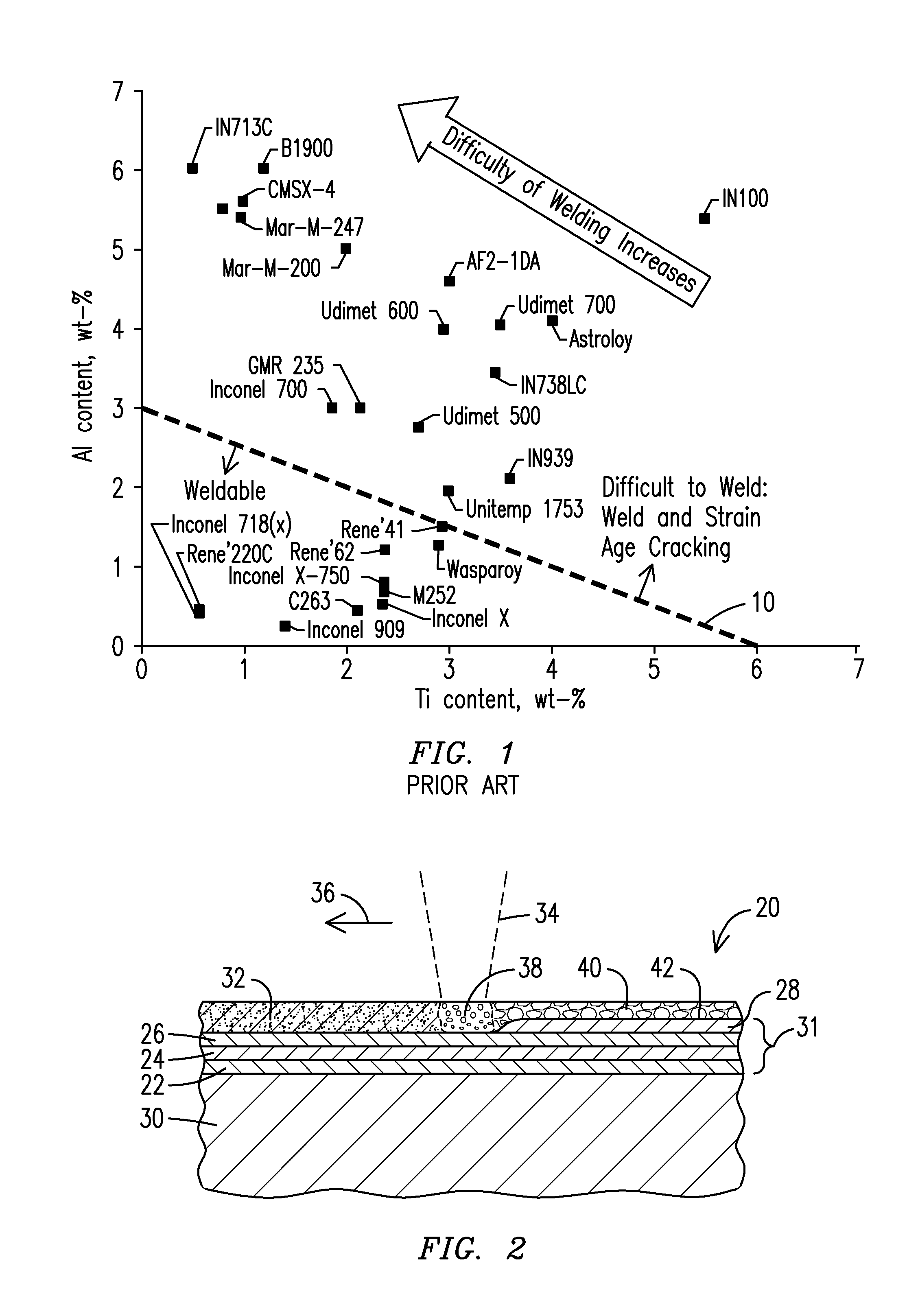
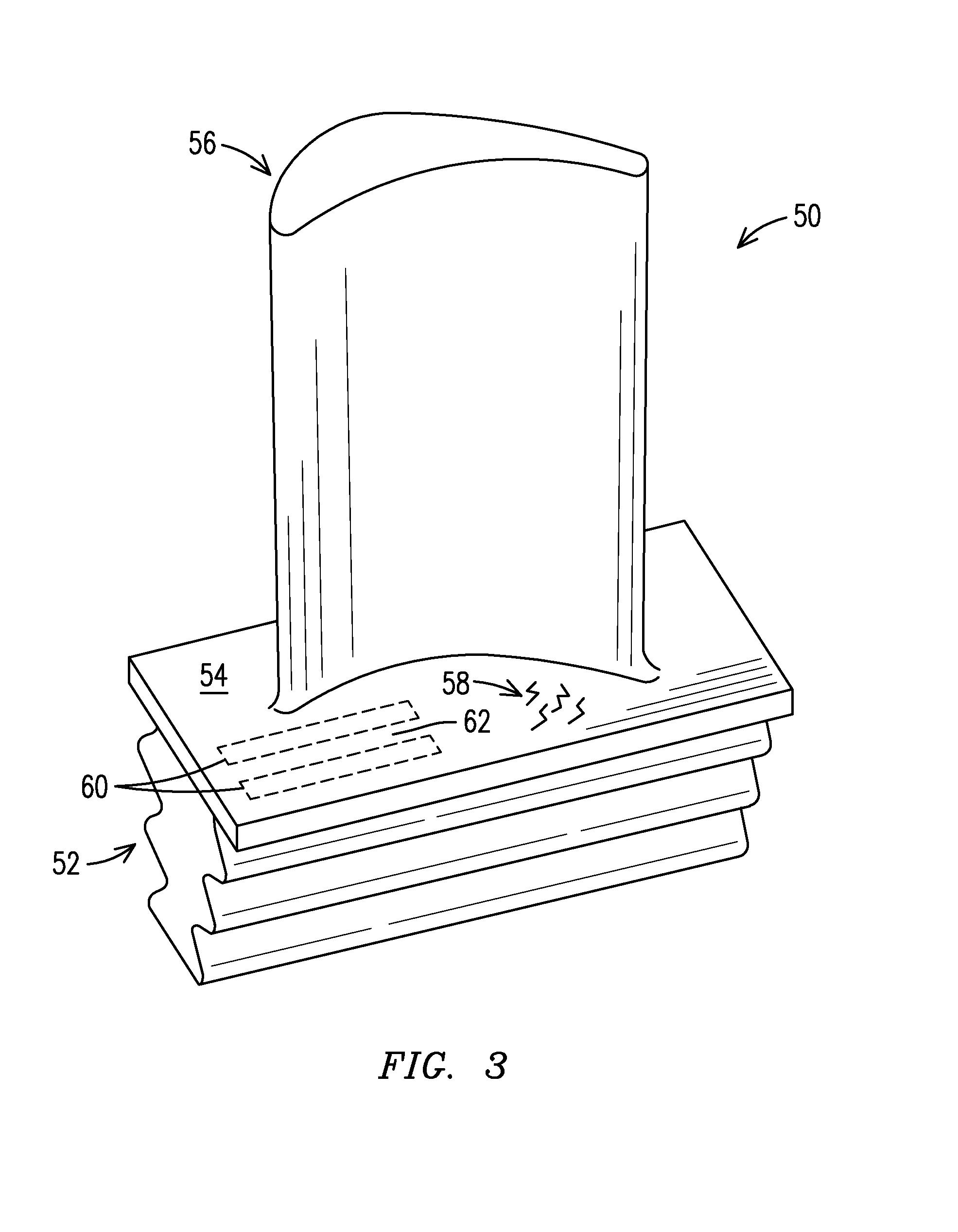
[0011]The repair of service-run superalloy gas turbine components has traditionally been restricted by the difficulty of weld repair of high alloy materials. United States Patent Application Publication No. US 2013 / 0136868 A1, incorporated by reference herein, discloses improved methods for depositing superalloy materials that are otherwise difficult to weld. Those methods include the laser melting of powdered superalloy material together with powdered flux material to form a melt pool under a layer of protective slag. The slag performs a cleaning function in addition to protecting the molten alloy material from the atmosphere. Upon solidification, the slag is removed from the newly deposited superalloy material to reveal a crack-free surface. Such methods have been shown to be effective even for superalloy materials which are beyond the traditional zone of weldability shown in FIG. 1

[0012]The present inventors now extend the capability described in United States Patent Application ...


PUM

PropertyMeasurementUnit
thicknessaaaaaaaaaa
compositionaaaaaaaaaa
porosityaaaaaaaaaa

Abstract

A method of repairing or manufacturing a superalloy component (50) by depositing a plurality of layers (22, 24, 26, 28) of additive superalloy material having a property that is different than an underlying original superalloy material (30). The property that is changed between the original material and the additive material may be material composition, grain structure, principal grain axis, grain boundary strengthener, and / or porosity, for example. A region (60) of the component formed of the additive material will exhibit an improved performance when compared to the original material, such as a greater resistance to cracking (58).

Description

[0001]This application is a continuation-in-part of co-pending U.S. patent application Ser. No. 14 / 071,774 filed 5 Nov. 2013 (attorney docket 2013P14584US) This application is also a continuation-in-part of co-pending U.S. patent application Ser. No. 14 / 144,680 filed 31 Dec. 2013 (attorney docket 2012P28296US01), which in turn claimed benefit of the 31 Jan. 2013 filing date of U.S. provisional patent application No. 61 / 758,795 (attorney docket 2012P28296US). This application is also a continuation-in-part of co-pending U.S. patent application Ser. No. 13 / 956,431 filed 1 Aug. 2013 (attorney docket 2013P03470US), which in turn was a continuation-in-part of U.S. patent application Ser. No. 13 / 755,098 filed on 31 Jan. 2013 (attorney docket 2012P28301US) which in turn was a continuation-in-part of U.S. patent application Ser. No. 13 / 005,656 filed on 13 Jan. 2011 (attorney docket 2010P13119US).FIELD OF THE INVENTION[0002]This invention relates generally to the field of materials technolog...

Claims


Application Information

Patent Timeline
Patent Type & Authority Applications(United States)
IPC IPC(8): C23C28/02
CPCC23C28/021C23C24/106F01D5/005B23K26/34B23K26/211B23K2101/001Y10T428/12986
Inventor KAMEL, AHMEDBRUCK, GERALD J.JOUINI, DHAFER
Owner SIEMENS ENERGY INC
Why Eureka
Try Eureka