Machining Method for Hard-Fine Machining of Noise-Optimized Gears on a Gear-Cutting Machine

a gear-cutting machine and hard-fine machining technology, which is applied in the direction of gear teeth, gear manufacturing apparatus, manufacturing tools, etc., can solve the problems of insufficient direct production of waviness, inflexible profiling type, and high labor intensity of profiling gear modification, so as to avoid or at least minimize the vibration excitation of transmission, and increase the uniformity of rotational movement

Active Publication Date: 2014-09-11
LIEBHERR VERZAHNTECHNIK GMBH
View PDF3 Cites 29 Cited by
  • Summary
  • Abstract
  • Description
  • Claims
  • Application Information

AI Technical Summary

Benefits of technology

[0014]The objective of the application is now to increase the uniformity of the rotational movement and thus to avoid or at least minimize the vibration excitation of the transmission.

Problems solved by technology

Using a profiling gear in accordance with this description, 3-dimensional corrections on the tooth flanks are first able to be transferred to the worm grinding wheel and from there onto the ground workpiece again This type of profiling is, however, very inflexible since first a suitable 3-dimensionally corrected profiling gear has to be produced so that then its surface structure can in turn be transferred via the worm grinding wheel to the finished gear.
Modifications to the profiling gear are very labor-intensive and can thus not be implemented in the short term in a mass-production process.
This process is, however, not sufficient alone directly to produce waviness on the tooth flanks of a ground gear.
However, the combination of the two machining methods alone is not sufficient for the increased demands made today on the smooth running of a gear in a transmission.
The number of required stroke movements for machining an individual tooth flank and the associated high time effort per workpiece are disadvantageous in this method.
This irregularity of the rotational movement results in a vibration excitation of the transmission system.

Method used


Image

  • Machining Method for Hard-Fine Machining of Noise-Optimized Gears on a Gear-Cutting Machine
  • Machining Method for Hard-Fine Machining of Noise-Optimized Gears on a Gear-Cutting Machine
  • Machining Method for Hard-Fine Machining of Noise-Optimized Gears on a Gear-Cutting Machine

Examples


Embodiment Construction

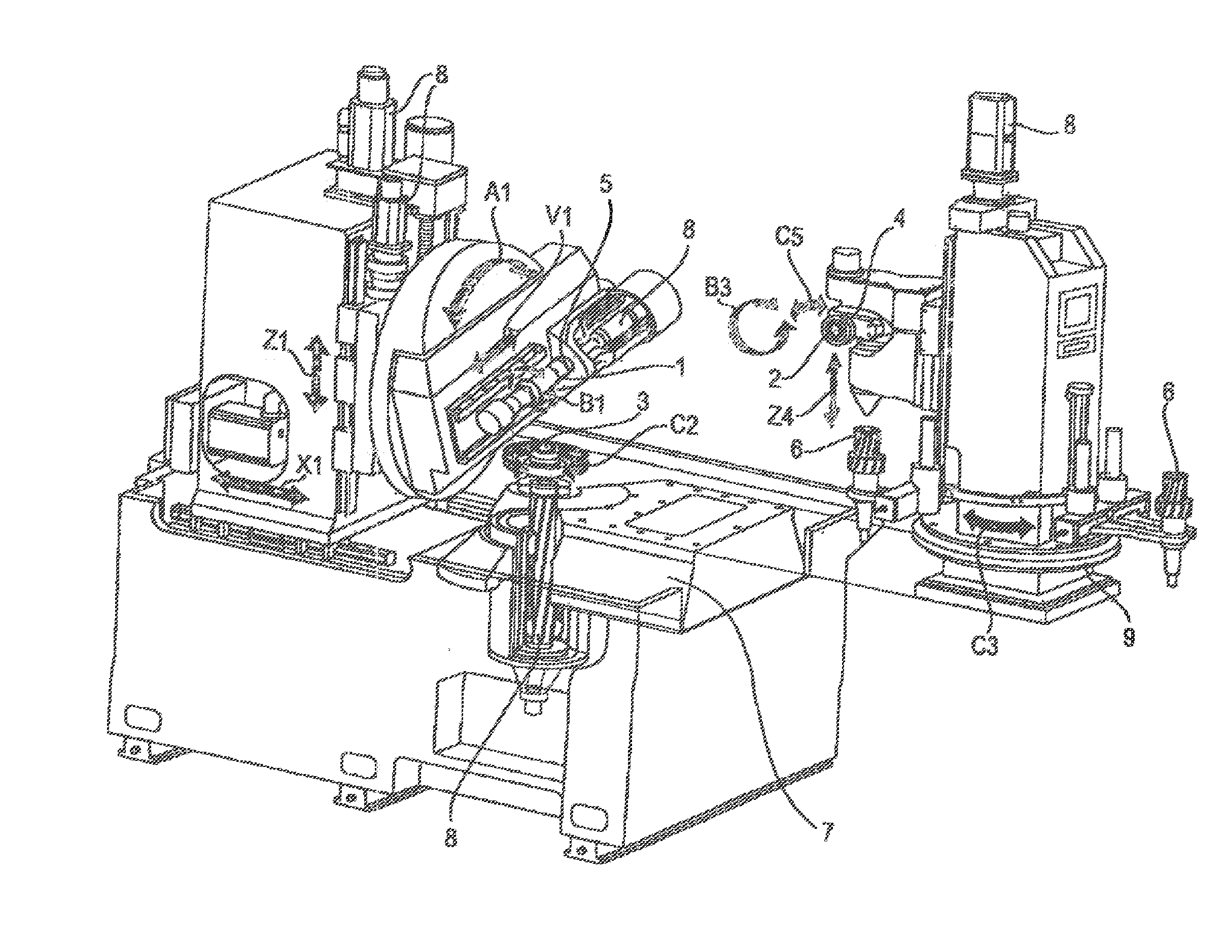
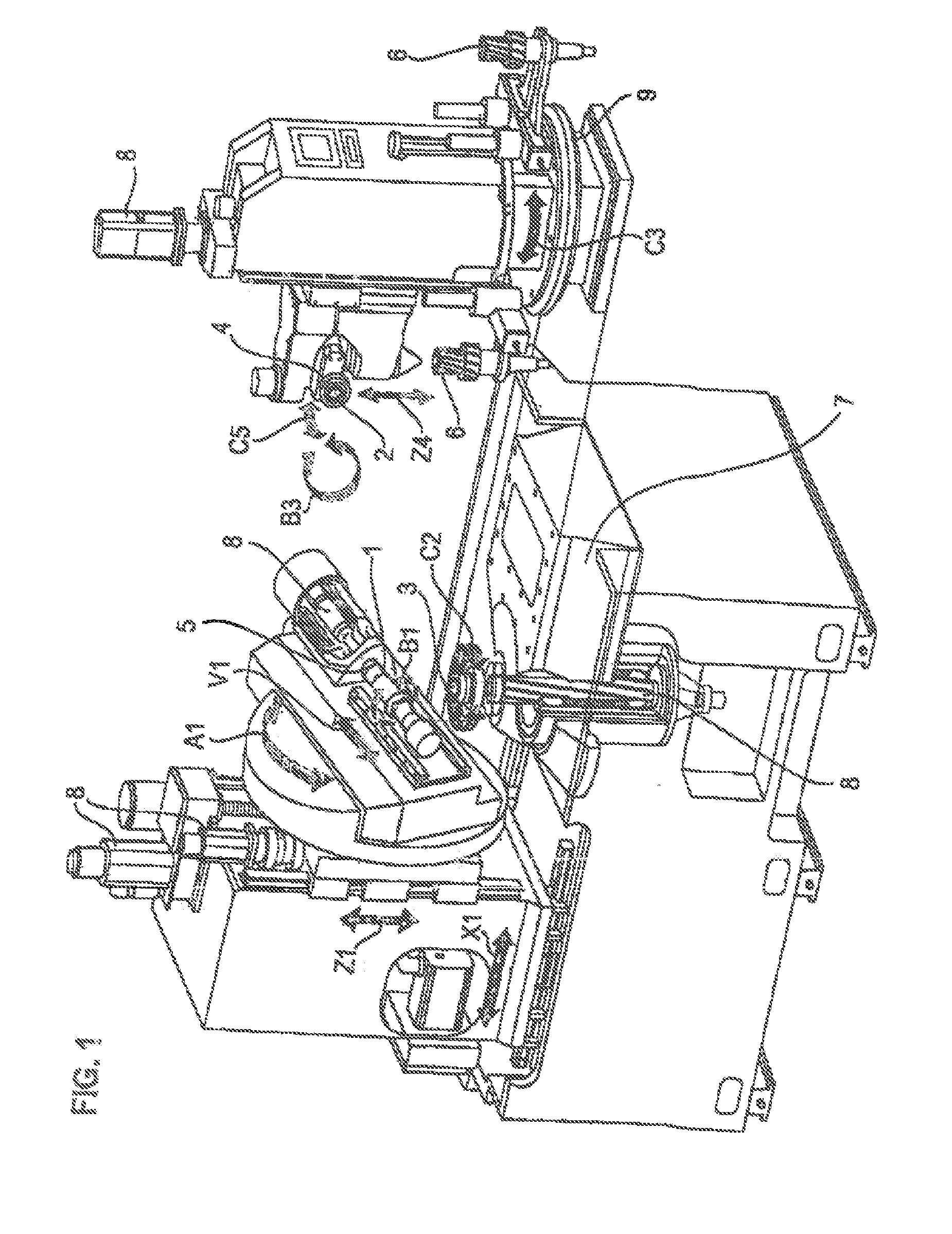
[0032]FIG. 1 shows a perspective view of a gear-cutting machine, in particular of a gear grinding and profile grinding machine for carrying out the methods in accordance with the invention for manufacturing a profile modification or profile waviness, in particular a periodic flank waviness, on a workpiece to be gear cut. The gear cutting machine in this respect has the degrees of freedom required for the machining and can in particular carry out the drawn movements A1, B1, B3, C2, C3, C5, V1, X1, Z1 and Z4. In detail, XI describes the radial movement of the pedestal carriage; V1 the tangential movement or shift movement of the tool; Z1 the axial movement of the tool; B1 the rotational movement of the tool; C2 the rotational movement of the workpiece; A1 the pivot movement of the tool; Z4 the vertical movement of the counter-holder; C3 the rotational movement of the ring charger; B3 the rotational movement of the dressing tool; and C5 the pivot angle of the dressing tool for varying ...


PUM

PropertyMeasurementUnit
distance erroraaaaaaaaaa
frequencyaaaaaaaaaa
surface structureaaaaaaaaaa

Abstract

The present invention relates to a method for hard-fine machining of tooth flanks with corrections and/or modifications on a gear-cutting machine, wherein respective toothed wheel pairings which mesh with one another within a transmission or a test device are machined while taking account of the respective mating flanks, and wherein the tooth flanks of the relevant workpieces are provided with periodic waviness corrections or waviness modifications. In accordance with the invention, the rotational error extent is determined by means of rotational distance error measurement of the toothed wheel pairs in a gear measuring device and/or transmission. This measurement result serves as an input value for defining the amplitude, frequency and phase position for the periodic flank waviness corrections on the tooth flanks of the toothed wheel pairings for production in the gear-cutting machine.

Description

BACKGROUND OF THE INVENTION[0001]The invention relates to a method for gear grinding and / or gear honing of noise-optimized gears on a gear-cutting machine, to the associated measuring method and to the control software for the corresponding control of the gear-cutting machine.[0002]The demands on modern transmissions with respect to construction size, noise behavior and transferrable powers are increasing more and more. The demands on the production precision of the installed gear wheels thus also increase inter alia. To satisfy these demands, the gear wheels are provided in many cases in manufacture with a targeted modified flank geometry which differs from the purely involute flank geometry. The modifications are designed in this respect such that they positively influence the running smoothness and the transfer behavior of the transmission under load pressure conditions.[0003]The running noise of a transmission is determined at crucial points from the excitation or from the vibra...

Claims


Application Information

Patent Timeline
Patent Type & Authority Applications(United States)
IPC IPC(8): B23F1/02B23Q15/02
CPCB23Q15/02B23F1/02B23F17/001B23F19/002B23F23/1218B23F5/04
Inventor GEISER, HANSJORG
Owner LIEBHERR VERZAHNTECHNIK GMBH
Why Eureka
Try Eureka