
Combination solar thermal and photovoltaic module

Inactive Publication Date: 2014-09-18
FAFCO INC
View PDF5 Cites 2 Cited by
  • Summary
  • Abstract
  • Description
  • Claims
  • Application Information

AI Technical Summary

Benefits of technology

The present invention provides a solar module that integrates a photovoltaic module and a thermal solar module, allowing for better performance and improved reliability. The module is made with an amorphous material that is semi-viscous and free from any imperfections, allowing for thermal expansion and contraction of either or both the photovoltaic module and the solar thermal module during operation. The module is lightweight, corrosion resistant, and can withstand high wind load with minimal roof penetrations. The invention also allows for low-cost installations, providing a flexible solution for various applications. Overall, the invention provides a stable and efficient solar energy solution that integrates multiple components to achieve improved performance.

Problems solved by technology

As the population of the world explodes, industrial expansion has lead to an equally large consumption of energy.
Unfortunately, other sources such as nuclear has lead to catastrophic events such as the 2011 Fukushima Daiichi nuclear disaster, Chernobyl disaster, among others.
Although solar panels have been used successful for certain applications, there are still certain limitations.
Solar cells are often costly.
Depending upon the geographic region, there are often financial subsidies from governmental entities for purchasing solar panels, which often cannot compete with the direct purchase of electricity from public power companies.
Such wafer materials are often costly and difficult to manufacture efficiently on a large scale.
Availability of solar panels is also somewhat scarce.
That is, solar panels are often difficult to find and purchase from limited sources of photovoltaic silicon bearing materials.

Method used


Image

  • Combination solar thermal and photovoltaic module
  • Combination solar thermal and photovoltaic module
  • Combination solar thermal and photovoltaic module

Examples


example

[0150]To prove the operation of the present invention, experiments were performed in one or more examples. These are merely examples, which should not unduly limit the scope of the claims herein. One of ordinary skill in the art would recognize other variations, modifications, and alternatives. In an example under subcontract No. AEU-2-22001-01, Integrated PV / Thermal System for Naval Base Guam, to support a partnership between the U.S. Navy's Naval Facilities Engineering Command (NAVFAC) and the National Renewable Energy Laboratory (NREL) to demonstrate leading-edge, cost-effective commercial energy technologies that can enable the Department of Defense (DoD) to meet its renewable energy goals and enhance its installation energy security.

[0151]In an example, a demonstration FAFCO integrated photovoltaic (PV) / thermal system, capable of 7-15 W / ft2 DC power generation at one sun (1,000 W / m2), 45-60 W / ft2 thermal power generation at one sun, and an estimated energy savings of roughly 85...


PUM

PropertyMeasurementUnit
Lengthaaaaaaaaaa
Lengthaaaaaaaaaa
Fractionaaaaaaaaaa

Abstract

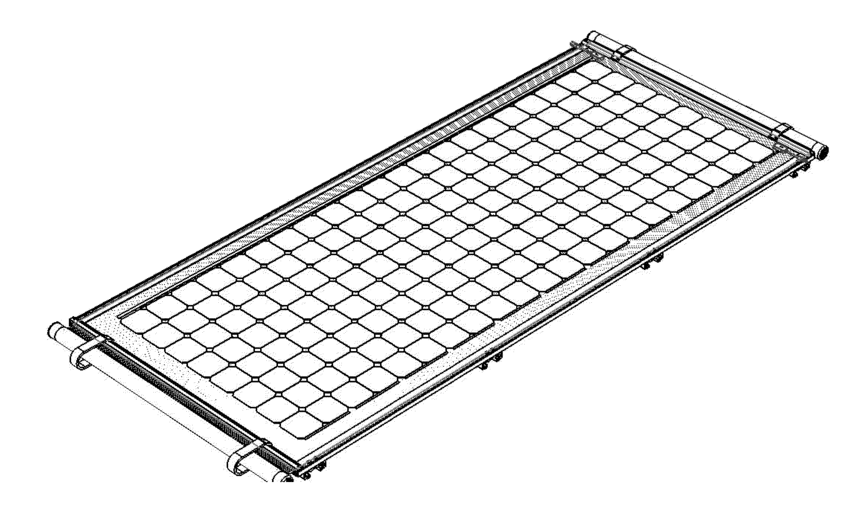
An integrated solar thermal and photovoltaic apparatus. The apparatus includes a solar thermal module, and a photovoltaic module comprising a plurality of solar cells configured in a polymeric material. The apparatus has an amorphous material configured between the thermal solar module and the photovoltaic module. The amorphous material has a semi-viscous, thermally conductive, and mastic characteristic to allow for thermal expansion and contraction of either or both the photovoltaic module or the solar thermal module during an operating time. The apparatus has an aperture region provided on a first side of the photovoltaic module and the solar thermal module is overlying a second side of the photovoltaic module. The thermal solar module, the photovoltaic module, and the amorphous material form an integrated thermal solar module.

Description

CROSS-REFERENCE TO RELATED APPLICATIONS[0001]This application claims priority to U.S. Ser. No. 61 / 778,204 (Attorney Docket No. A943R0-000100PV) filed Mar. 12, 2013, commonly assigned, and hereby incorporated by reference for all purposes.GOVERNMENT RIGHTS[0002]This invention was made by support of the U.S. Government Alliance for Sustainable Energy, LLC Management and Operating Contractor For the National Renewable Energy Laboratory (“NREL”) under Subcontract No. AEU-2-22001-01, and the U.S. Government may have certain rights in this invention.BACKGROUND OF INVENTION[0003]The present invention relates generally to solar energy techniques. More particularly, the present invention provides a method and apparatus for generating energy by way of a combination of photovoltaic and thermal solar conversion devices. Merely by way of example, the invention has been applied to a solar module, but it would be recognized that the invention has a much broader range of applicability.[0004]As the ...

Claims


Application Information

Patent Timeline
IPC IPC(8): H01L31/0525H05K13/00
CPCH05K13/0023H01L31/058H02S40/44Y02E10/50H01L31/048H02S30/10H02S40/34B32B27/08Y02E10/44Y02E10/60F24S40/80F24S2025/601F24S10/501Y10T29/49002H01L31/0521
Inventor RUBIO, MICHAEL R.WARD, ALEXANDER
Owner FAFCO INC
Learn More