Method and apparatus for control of a plasma for spectrometry

a technology of plasma and control signal, applied in the direction of mass spectrometer, particle separator tube, spectrum investigation, etc., can solve the problems of affecting the control of the plasma, slow response to changes in conditions, and possible spectral interference, so as to facilitate stable and precise feedback control, accurate method of controlling temperature, and the effect of more precise control signal

Active Publication Date: 2014-09-18
THERMO ELECTRON MFG
View PDF0 Cites 4 Cited by
  • Summary
  • Abstract
  • Description
  • Claims
  • Application Information

AI Technical Summary

Benefits of technology

[0019]The invention provides an improved method and apparatus for controlling the temperature of the plasma, providing greater signal stability. Preferably the two spectral lines of radiation emitted by the plasma are spectral lines from the same element; for example, the element may be an element present in the gas used to sustain the plasma, or it may be an element present in an internal standard introduced into the plasma. Where optical emissions from ionized elements are to be measured, stability of the temperature is important as it affects the ionization efficiency. Preferably one of the two spectral lines of radiation measured using the method of the invention is a spectral line from an ionized element, hence preferably one of the spectral lines is from an element in atomic form and the other spectral line is from an element in ionic form.
[0020]Alternatively, at low plasma powers, some elements may not have appreciable concentrations of ionized species present in the plasma. In these circumstances it may be preferable that both spectral lines are from an element which is not present in ionic form in the plasma at a relative concentration to the unionized form of greater than 1%. A more accurate method of controlling the temperature of the plasma is thereby achieved as a ratio of two similar intensities where both the intensities are well above the noise limit provides a more precise control signal.
[0021]Advantageously, by using more than two lines spread over the wavelength range of the instrument it is possible to not only maintain a constant plasma temperature but also to diagnose wavelength-dependent transmission problems in an ICP-OES spectrometer, such as may be caused, for wavelengths below 190 nm, by the presence of oxygen in the wavelength selector. Hence preferably one of the spectral lines is of a wavelength below 190 nm.
[0022]To facilitate stable and precise feedback control of the power provided to sustain the plasma, preferably the ratio of the intensities of the two measured spectral lines of radiation emitted by the plasma and which are used to control the power is between 0.1 and 10.
[0027]In another preferred embodiment, the wavelength selector comprises two optical filters and a detector system, one optical filter for transmitting a first optical wavelength onto the detector system, the other optical filter for transmitting a second optical wavelength onto the detector system, the combination of the two optical filters and the detector system providing the wavelength selector. The embodiment utilizing the combination of two optical filters and a detector system to provide the wavelength selector is relatively low cost and is particularly suitable for use with ICP-MS and MIP-MS systems which do not ordinarily already comprise an optically dispersive element and detector system.

Problems solved by technology

When multiple elements are present there is the possibility of spectral interference (where one spectral line overlaps another).
In the former case, the matching network is usually electromechanical and so it is slow to respond to changes in conditions.
The change in frequency causes a change in power delivered to the plasma, which is undesirable, but this may be compensated for by the instrument controller which may monitor the voltage and current driven through the coil.
It has been found that controlling the plasma power in this way does not however fully stabilize the detected optical and mass signals from sample material.
The transmission of optical emission from the plasma varies over time due to contamination of optical elements, and this method of plasma control is unsuitable to provide significant benefits over other prior art methods involving RF power control.

Method used


Image

  • Method and apparatus for control of a plasma for spectrometry
  • Method and apparatus for control of a plasma for spectrometry
  • Method and apparatus for control of a plasma for spectrometry

Examples


Embodiment Construction

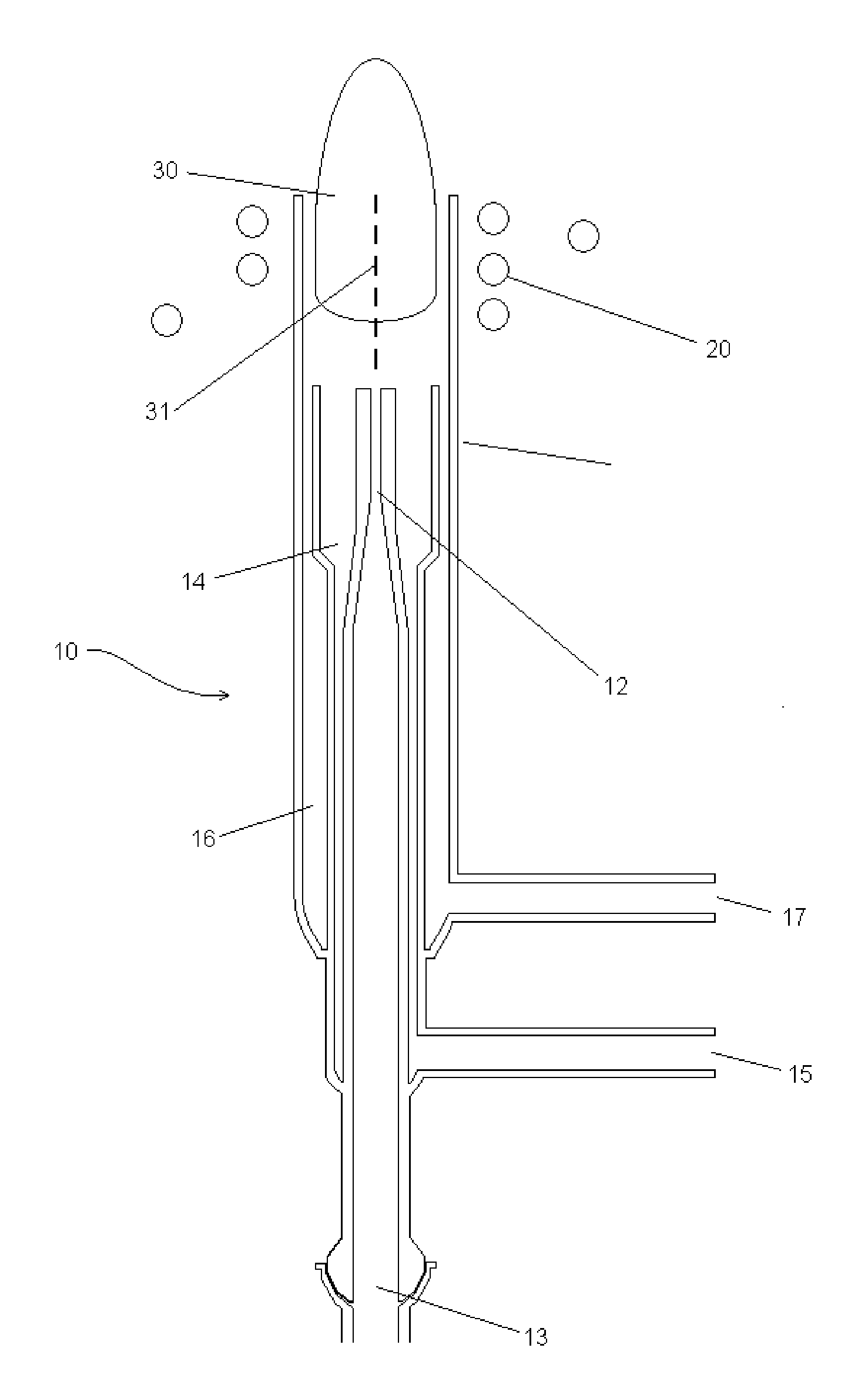
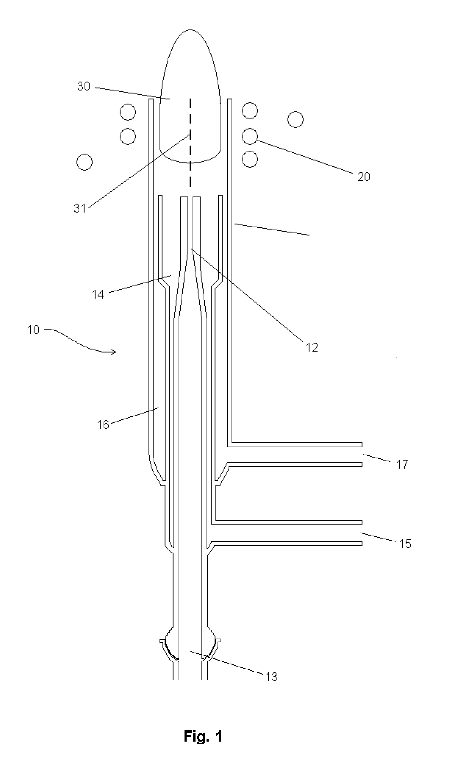
[0034]FIG. 1 is a schematic cross sectional diagram of a prior art torch and RF coil for an inductively coupled plasma for optical emission spectrometry or for mass spectrometry. Torch 10 comprises injector tube 12, auxiliary tube 14 and outer tube 16. Typically torch 10 is made of quartz glass or ceramic elements. The gas flow entering injector tube 12 at inlet 13 is known as an injection gas. Additional gas is supplied to auxiliary tube 14 via inlet 15, and this gas flow is known as auxiliary gas. A further gas flow is supplied to outer tube 16 via inlet 17, and this gas flow is known as the cool gas, as it is predominantly used to introduce a barrier of gas along the inside surface of outer tube 16. All three gases typically comprise argon. ICP coil 20 is used to couple RF power (typically, at 27 MHz) into a plasma 30 formed within and emerging from outer tube 16. Droplets or solid particles entering the inlet of torch 10 via injector tube 12 are transported in the injector gas i...


PUM


Abstract

A method of and apparatus for controlling the temperature of an inductively coupled or microwave induced plasma for optical emission spectrometry or mass spectrometry in which the intensities of two spectral lines of radiation emitted by the plasma are measured, and the power provided to sustain the plasma is adjusted so that the ratio of the intensities remains substantially constant.

Description

FIELD OF THE INVENTION[0001]This invention relates to the control of a plasma for spectrometry and in particular to control the plasma temperature and free electron density. The invention may be used to control inductively coupled plasmas and microwave induced plasmas, such as are used in optical emission spectrometry (ICP-OES and MIP-OES) and in mass spectrometry (ICP-MS and MIP-MS).BACKGROUND TO THE INVENTION[0002]ICP-OES, MIP-OES, ICP-MS and MIP-MS are well known techniques for elemental analysis of samples providing quantified determinations of elements present in liquid or solid samples trace levels (ppb or ppt). Small particles of solid sample or droplets of liquid sample are introduced into a plasma whereupon they are atomized, excited, and a proportion are ionized. Excited atoms and ions emit photons characteristic of the elements present and the optical emission produced is analyzed in ICP-OES and MIP-OES using an optical spectrometer. Ions are introduced into a vacuum syst...

Claims


Application Information

Patent Timeline
Patent Type & Authority Applications(United States)
IPC IPC(8): H01J37/244H01J49/26G01J3/443H01J37/08
CPCH01J37/244H01J49/26H01J37/08G01J3/443H01J27/16H01J37/32972H01J49/105H05H1/0037G01J2003/4435H01J37/3299
Inventor HARTWELL, STEPHEN
Owner THERMO ELECTRON MFG
Why Eureka
Try Eureka