Instant Entropy System

Inactive Publication Date: 2014-09-18
IENTROPIA SPA
View PDF4 Cites 2 Cited by
  • Summary
  • Abstract
  • Description
  • Claims
  • Application Information

AI Technical Summary

Benefits of technology

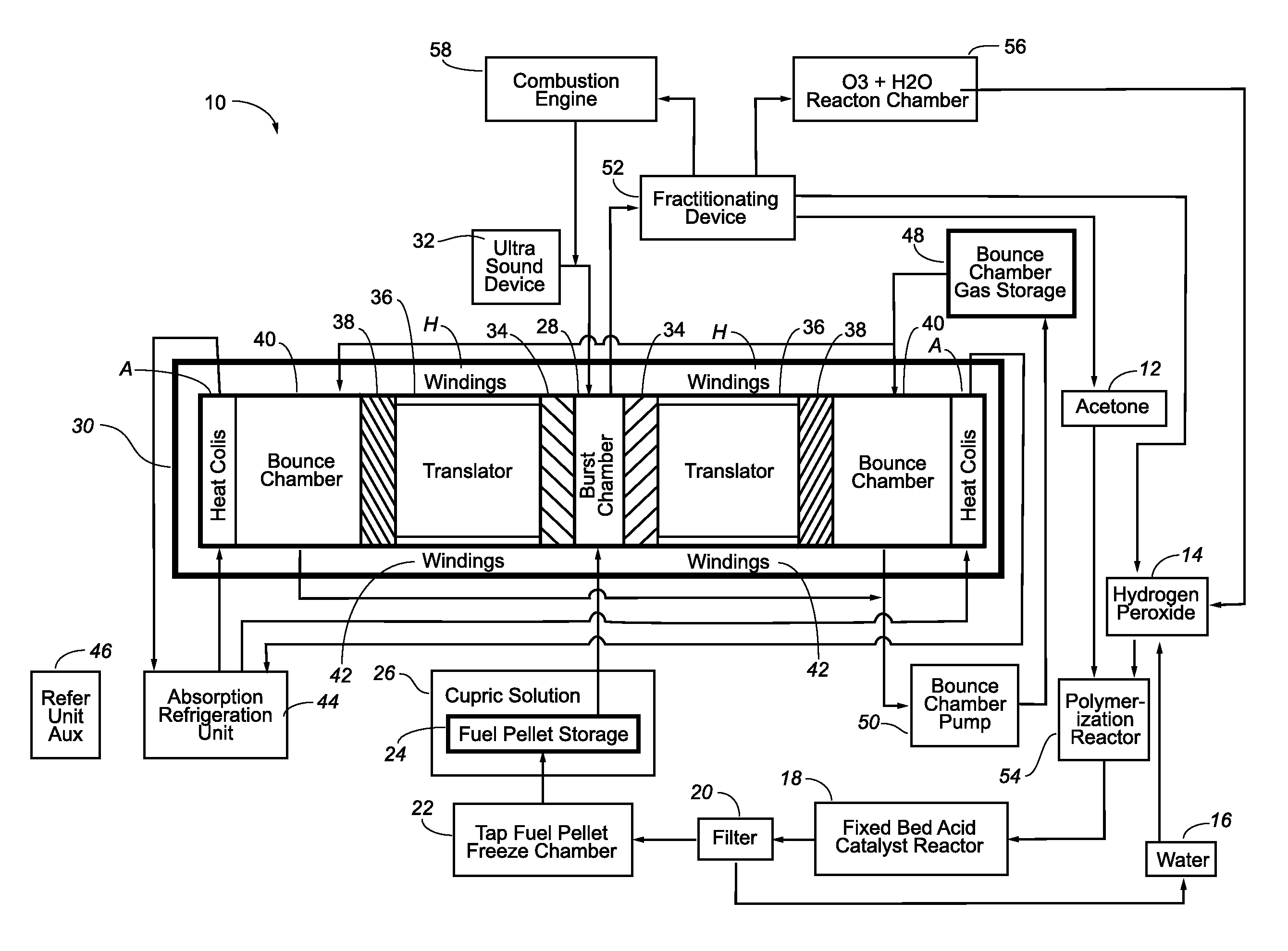
[0014]To make TAP suitable for use in the IES, acetone (99%) and hydrogen peroxide (50%) are combined in a temperature controlled environment. This solution, polymerized acetone and water, is passed through a fixed bed acid catalyst, during which the solution temperature is held below 0° C. This is in contrast to the typical use of liquid acid catalyst. The TAP crystals are formed as the polymerized acetone contacts the solid acid catalyst resulting in solid TAP crystals in water. The water is removed using filtration such that the TAP volume is in a specific percentage relationship to the water. This percentage is dependent on the device to be driven, that is, whether turbine or internal combustion engine. The TAP solution is then cooled at a specific rate to control the water crystallization size, creating a frozen TAP fuel pellet. The frozen TAP fuel pellet has increased stability and decreased sublimation. Because this fuel pellet has been cooled at a specific rate to a specific dimension, there is a constant dominant resonant frequency that can be employed to readily initiate the entropy burst of the TAP fuel pellet. In the alternative the TAP fuel pellet may also be caused to EB via thermal and mechanical shock. This shock would be supplied by combusting the minor EB gases, ethane and methyl acetate, to produce superheated water. The superheated water injection upon the fuel pellet would subject the fuel pellet to sufficient mechanical and thermal shock (MTS) to initiate the EB. Depending on the required speed of the generator both bust initiation alternatives may be used in conjunction to reduce burst onset lag time.
[0015]The TAP fuel pellets are stored in a cryogenic chamber capable of being rapidly flooded with a copper/water solution should problems arise. The copper/water solution will nullify the TAP reactive potential. From storage, the TAP pellets are injected into the gas expansion chamber of the device to be driven.
[0016]The preferred embodiment of the combustion chamber is the combustion chamber of an opposed piston tubular linear generator (OPTLG), which are well known and need not be described in detail herein. However, it is worth noting that the major compo

Problems solved by technology

The fuel used by the inventive IES produces gas expansion, but not from an oxi

Method used


Image

  • Instant Entropy System
  • Instant Entropy System

Examples


Embodiment Construction

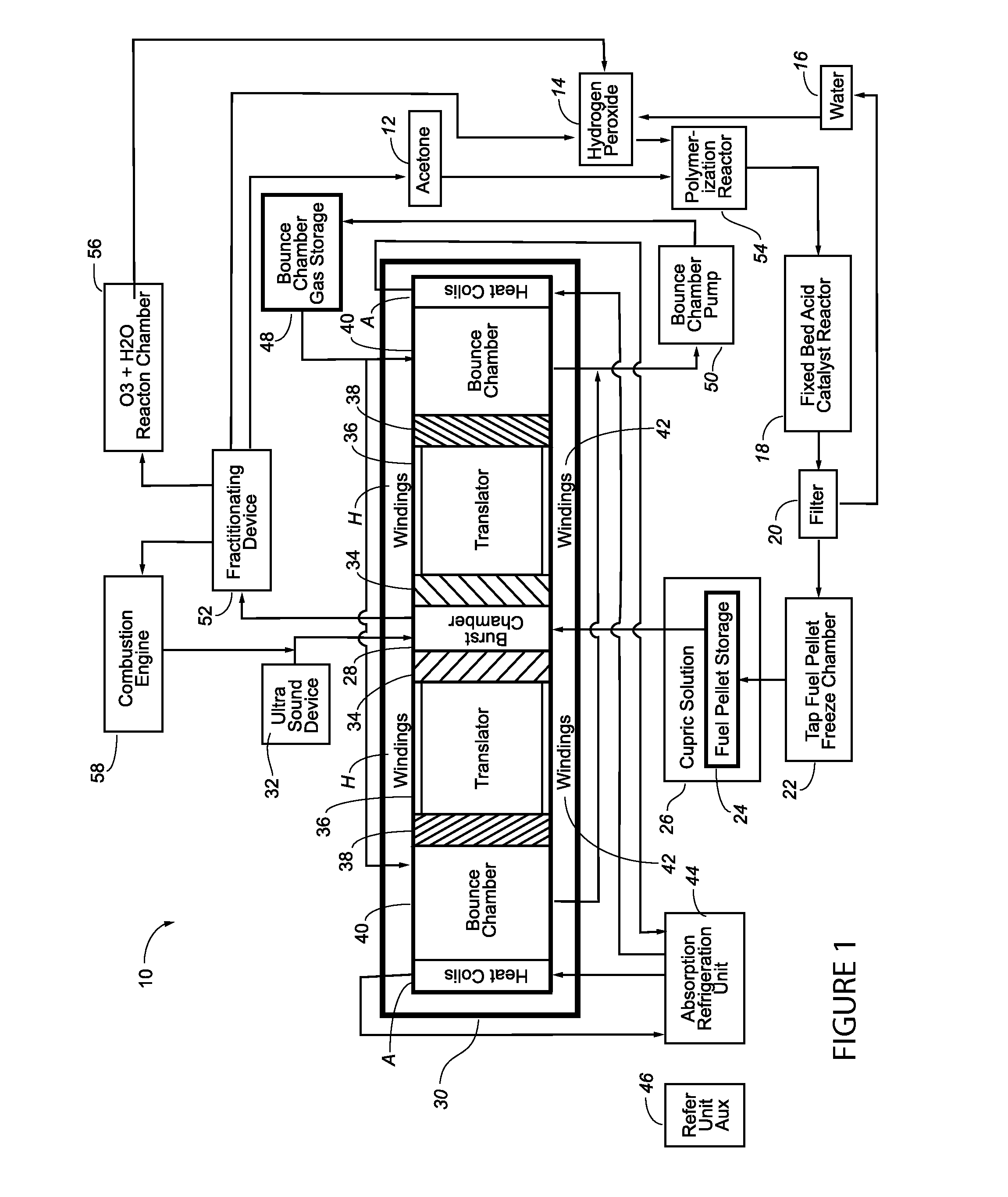
[0023]Referring now to FIG. 1, there is schematically illustrated in block diagrammatic form a preferred embodiment of the inventive IES. The system 10 preferably utilizes an opposed piston tubular linear generator (“OPTLG”) to generate electrical power. However, the IES will work in all internal combustion engines or turbine engines. It is particularly well suited for use in Prandtl turbines, also known as boundary layer turbines or Tesla turbines. The illustration herein represents the IES formation, work production, and gas recovery of the “entropy burst” (EB) of triacetone triperoxide (TAP).

[0024]TAP formation component chemicals are stored at 12 acetone, hydrogen peroxide 14, and water 16. The acetone and hydrogen peroxide are metered into a temperature controlled polymerization reactor 13. Once acetone polymerization has occurred, the acetone / water solution is metered through the fixed bed acid catalyst reactor 18. This reactor is held at a constant temperature, pressure, and ...


PUM


Abstract

The instant invention is to a new fuel system, which will allow operation of large scale electrical power generating facilities at a fraction of the cost of coal or natural gas fueled facilities and will not produce significant heat, exhaust emission gases, or particulate pollution. Because of the nature of the chemical reaction exploited in the system, it is denominated an instant entropy system (“IES”). The fuel used by the inventive IES produces gas expansion, but not from an oxidation/combustion reaction, and it does not produce oxidative exothermic heat. The IES utilizes a material first developed in the early part of the twentieth century—triacetone triperoxide (TAP).

Description

CROSS REFERENCES TO RELATED APPLICATIONS[0001]This application claims the benefit of U.S. Provisional Application 61 / 778,981, filed Mar. 13, 2013, entitled Instant Entropy System, which is incorporated herein by reference.BACKGROUND OF THE INVENTION[0002]1. Field of the Invention[0003]The present invention relates generally to electrical energy production and fuels for the same, and more particularly to an entropy burst fuel for use in electrical power generation facilities, and more particularly still to a system for using triacetone triperoxide pellets in an entropy burst generator for use in generating electricity.[0004]2. Background Discussion[0005]Modern society is based on (and largely depends on) the production of electricity from the combustion of carbon based fuels, principally coal and natural gas. These fuels are combusted / oxidized in central electrical power generation facilities that operate at fuel to electricity conversion efficiencies of less than 40%. The hot exhaus...

Claims


Application Information

Patent Timeline
IPC IPC(8): F02B63/04F02B45/08
CPCF02B45/08F02B63/04F01B11/004F01B11/007F01B11/02F02B71/00Y02T10/30
Inventor STONE, CHRISTOPHER S.
Owner IENTROPIA SPA
Why Eureka
Try Eureka