Cast-in cooling features especially for turbine airfoils

a technology of cooling features and turbine airfoils, which is applied in the direction of liquid fuel engines, foundry patterns, moulding apparatus, etc., can solve the problems of complex advanced cooling schemes, limited tooling design/fabrication capabilities, and complex core complexity of advanced high-thrust aircraft engines, so as to improve the efficiency of airfoil cooling

Active Publication Date: 2014-09-18
HOWMET CORPORATION
View PDF21 Cites 37 Cited by
  • Summary
  • Abstract
  • Description
  • Claims
  • Application Information

AI Technical Summary

Benefits of technology

[0010]The present invention provides a method useful for, although not limited to, making a mold for casting of advanced turbine airfoils (e.g. gas turbine blade and vane ...

Problems solved by technology

However, cooling schemes for advanced high-thrust aircraft engines are complex, often involving multiple, thin walls and non-planar cooling features.
The ceramic cores that define these advanced cooling schemes are conventionally formed by forcing ceramic compound into steel tooling, but core complexity is limited by the capabilities of tooling design/fabrication.
Therefore, complex advanced cooling schemes often rely on the assembly of multiple ceramic core pieces after firing.
Assembly requires specialized labor and results in core dimensional variability due to mismatch between assembled core components, while the fragile nature of fired cores results in elevated handling scrap, and compromises to the advanced cooling schemes are required to allow for assembly and positioning of the core assembly or multiple core pieces in the subsequent casting.
Forming multiple fugitive inserts and assembling them in a core die presents a similar problem to that cre...

Method used


Image

  • Cast-in cooling features especially for turbine airfoils
  • Cast-in cooling features especially for turbine airfoils
  • Cast-in cooling features especially for turbine airfoils

Examples


Embodiment Construction

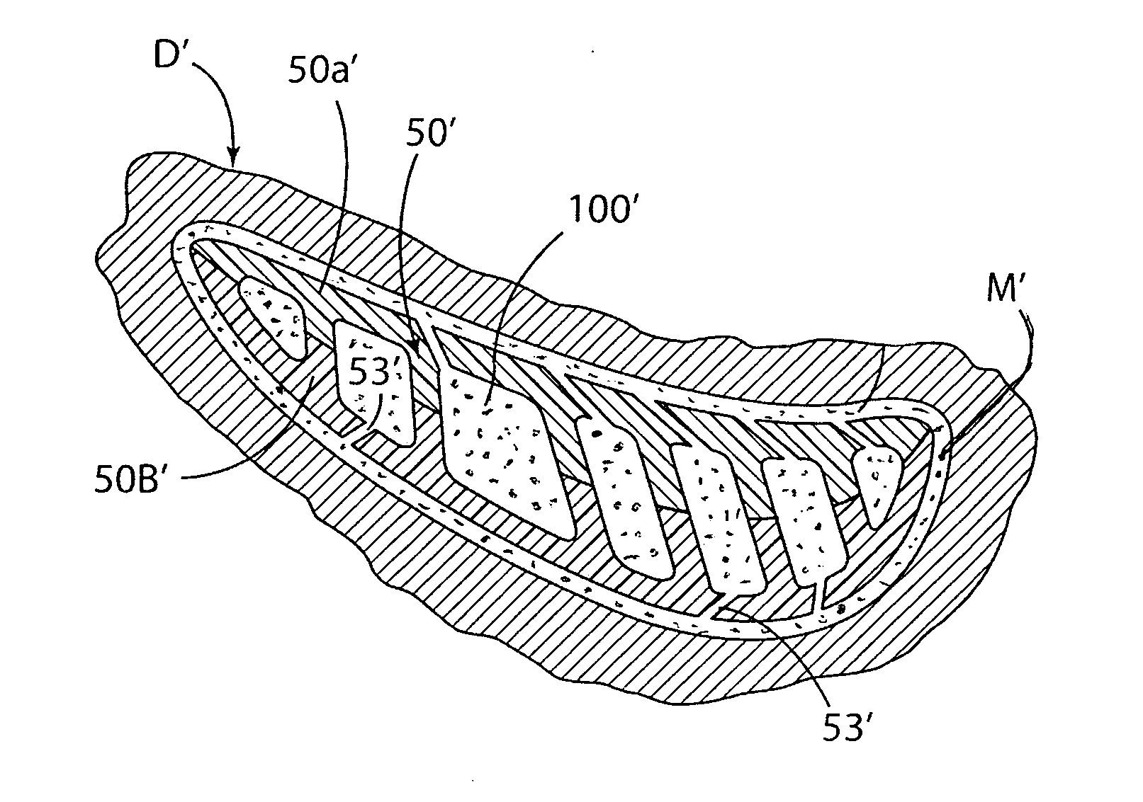
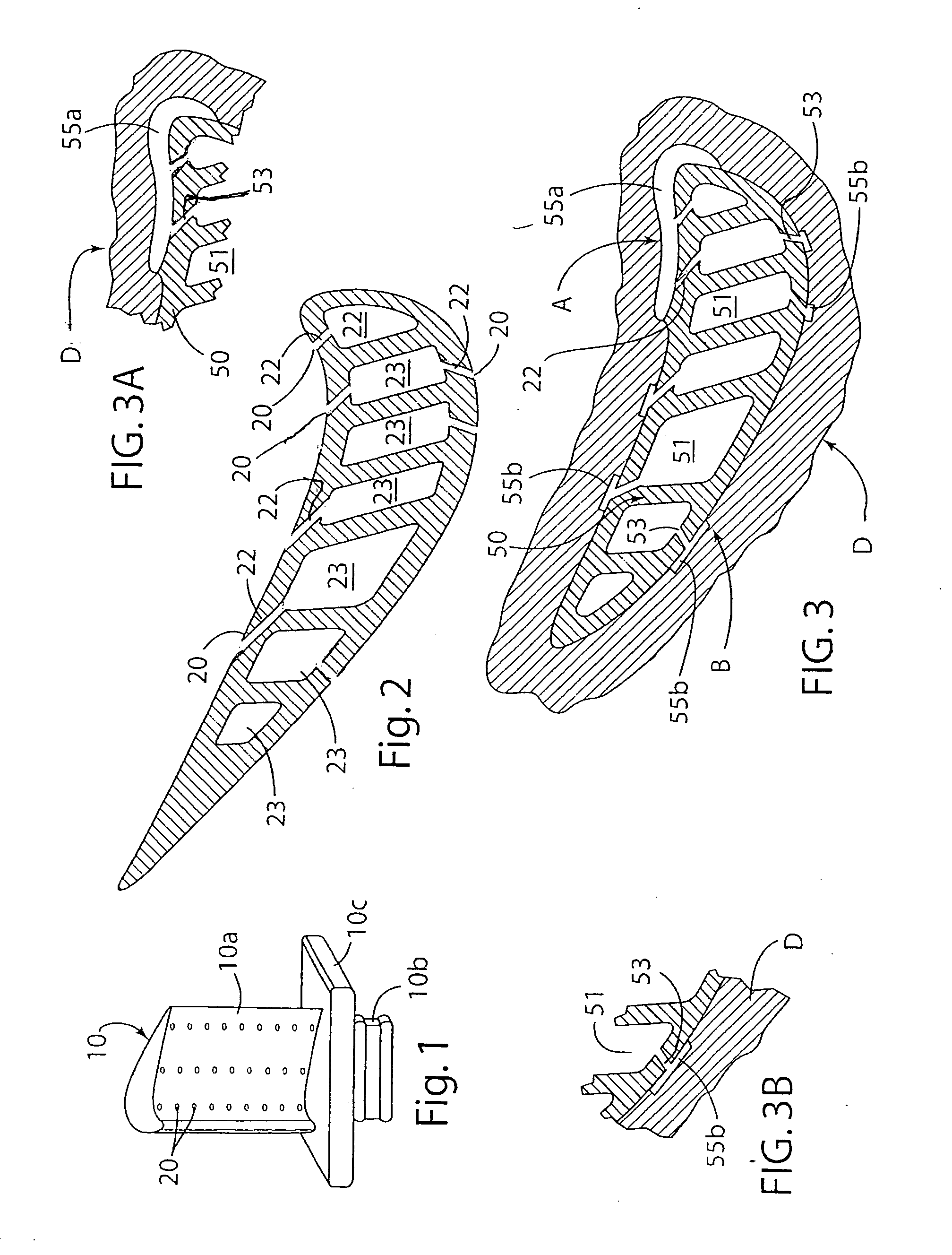
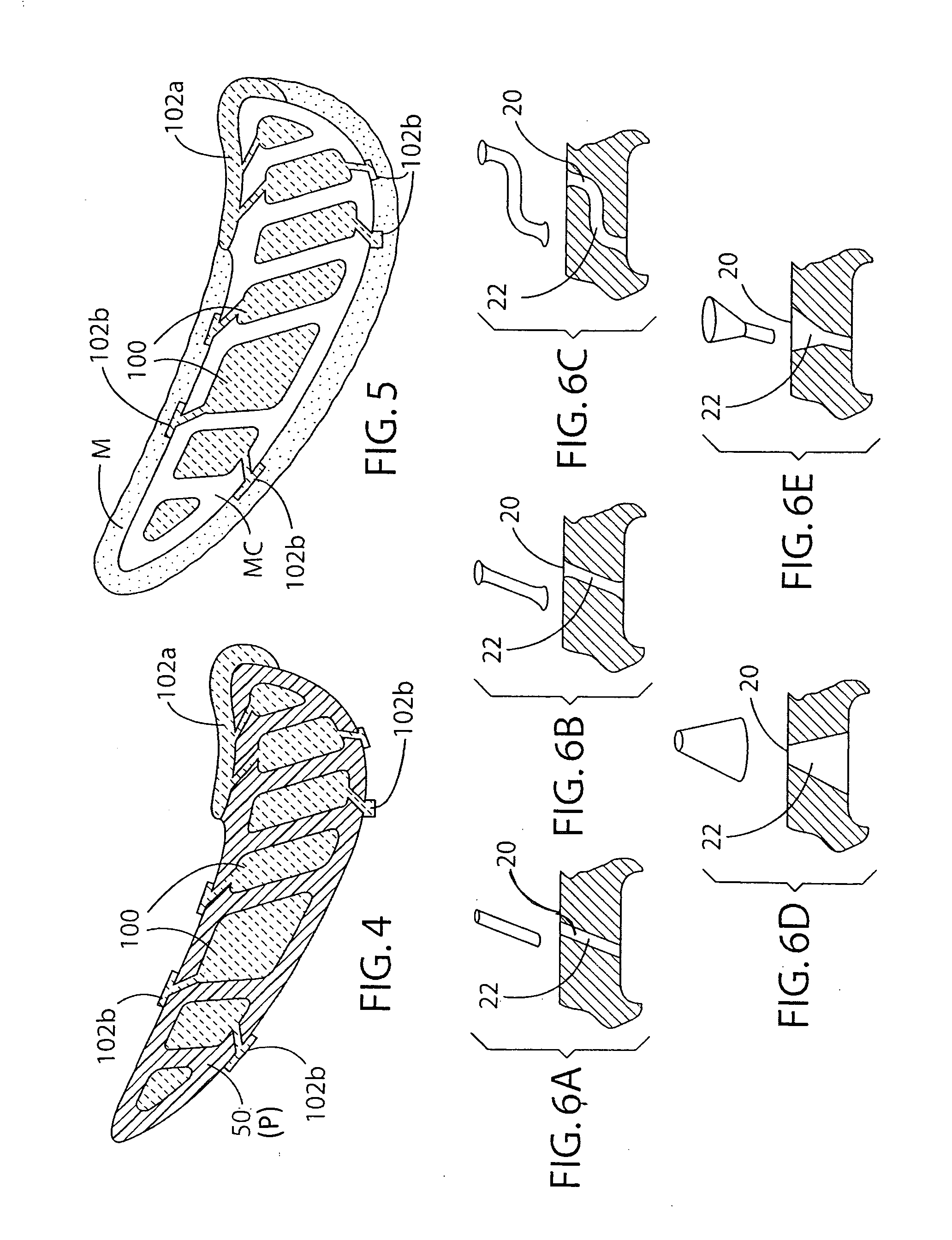
[0025]In order to make aero and / or industrial gas turbine engine airfoil cooling air schemes most effective, especially high pressure turbine blade and vanes (hereafter turbine airfoils), internal cooling features, such as air cooling passages, support pedestals, etc. as well as external cooling features, such as film cooling air exit holes, cooling-enhancing turbulators, etc. need to precisely partition and direct the cooling air such that its pressure is controlled and it is directed to the most needed regions of the blade or vane. Practice of the present invention permits production of complex airfoil geometries with complex cast-in internal and external cooling features and enhanced external casting wall thickness control.

[0026]Although the present invention will be described below in connection with the casting of advanced turbine airfoils (e.g. gas turbine blade and vane castings) which can include complex cast-in internal and external cooling air features to improve efficienc...


PUM

PropertyMeasurementUnit
Solubility (mass)aaaaaaaaaa
Efficiencyaaaaaaaaaa
Biodegradabilityaaaaaaaaaa

Abstract

A method is provided for making a mold for casting advanced turbine airfoils (e.g. gas turbine blade and vane castings) which can include complex internal and external air cooling features to improve efficiency of airfoil cooling during operation in the gas turbine hot gas stream. The method steps involve incorporating at least one fugitive insert in a ceramic material in a manner to form a core and at least a portion of an integral, cooperating mold wall wherein the core defines an internal cooling feature to be imparted to the cast airfoil and the at least portion of the mold wall has an inner surface that defines an external cooling feature to be imparted to the cast airfoil, selectively removing the fugitive insert, and incorporating the core and the at least portion of the integral, cooperating mold wall in a mold for receiving molten metal or alloy cast in the mold.

Description

FIELD OF THE INVENTION[0001]The present invention relates to the casting of metal or alloy articles of manufacture and more particularly, to a method of making a ceramic core and cooperating integral ceramic mold, or mold portion, useful though not limited to, the casting a turbine airfoil with cast-in cooling features and enhanced external casting wall thickness control.BACKGROUND OF THE INVENTION[0002]Most manufacturers of gas turbine engines are evaluating advanced multi-wall, thin-wall turbine airfoils (i.e. turbine blade or vane) which include intricate air cooling channels to improve efficiency of airfoil internal cooling to permit greater engine thrust and provide satisfactory airfoil service life. However, cooling schemes for advanced high-thrust aircraft engines are complex, often involving multiple, thin walls and non-planar cooling features. The ceramic cores that define these advanced cooling schemes are conventionally formed by forcing ceramic compound into steel toolin...

Claims


Application Information

Patent Timeline
IPC IPC(8): B22C9/10F01D5/18
CPCB22C9/10F01D5/187F01D5/186B22C7/02B22C9/04B22C21/14
Inventor MUELLER, BOYD A.PEPPER, MICHAEL A.ROGERS, DAREN K.COLE, GAIL R.
Owner HOWMET CORPORATION
Why Eureka
Try Eureka