
Dense composite material, method for producing the same, and component for semiconductor production equipment

Active Publication Date: 2014-09-18
NGK INSULATORS LTD
View PDF5 Cites 12 Cited by
  • Summary
  • Abstract
  • Description
  • Claims
  • Application Information

AI Technical Summary

Benefits of technology

The present invention provides a composite material with low expansion and high thermal conductivity, density, and strength. The dense composite material can be used as a component for semiconductor production equipment and can maintain high heat dissipation performance even after repeated use at low and high temperatures. The method for producing the dense composite material is also provided.

Problems solved by technology

However, since resin is an organic material, it has characteristics that it has a low heat dissipation property, is likely to decompose at high temperatures, and is likely to degrade with time.
Therefore, such an electrostatic chuck is hard to use in a high-temperature process for a long period of time.
However, unlike resin, metal is not soft, and it is not possible to relax stress caused by the difference in coefficient of linear thermal expansion between the electrostatic chuck and the cooling board.

Method used


Image

  • Dense composite material, method for producing the same, and component for semiconductor production equipment
  • Dense composite material, method for producing the same, and component for semiconductor production equipment

Examples


examples

[0028]Preferred examples of application of the present invention will be described below. As the SiC starting material, a commercially available product having a purity of 97% or more and an average particle size of 15.5 μm or 6.9 μm was used. A SiC starting material (Experimental Example 28) having an average particle size of 10.1 μm was prepared by mixing the SiC starting material with an average particle size of 15.5 μm and the SiC starting material with an average particle size of 6.9 μm at a ratio of 1:1. As the metallic Si starting material, a commercially available product having a purity of 97% or more and an average particle size of 9.0 μm was used. As the metallic Ti starting material, a commercially available product having a purity of 99.5% or more and an average particle size of 31.1 μm was used. As titanium disilicide, a commercially available product having a purity of 99% or more and an average particle size of 6.9 μm was used.

1. PRODUCTION PROCEDURE

[0029]Compounding...

experimental examples

2. EXPERIMENTAL EXAMPLES

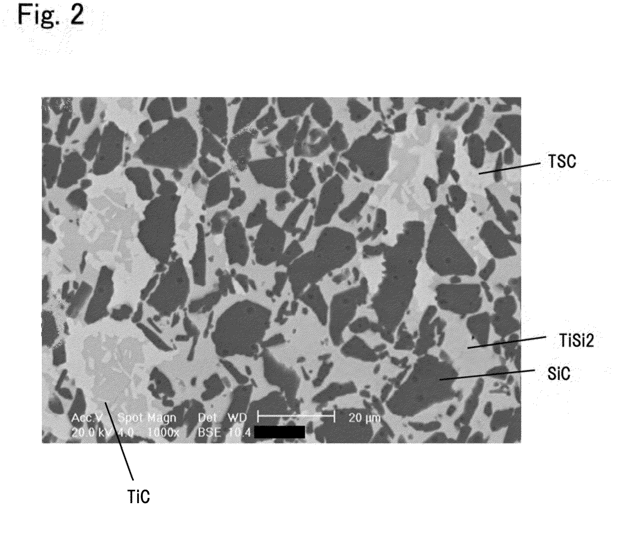
[0035]Tables 1 and 2 show, for the individual Experimental Examples, a: the starting material composition (mass ratio), b: the mass ratio of Si to the sum of Si and Ti (Si / (Si+Ti)), in which Si and Ti originate from starting materials, Si, Ti, and TiSi2, other than SiC, c: the average particle size of starting material SiC, d: hot-press firing temperature, e: presence or absence of liquid phase exudation during firing, f: the number of SiC grains having a major axis of 10 μm or more in an SEM image (backscattered electron image) magnified 1,000 times of a region with a size of 90 μm (length)×120 μm (width) of the dense composite material, g: constituent phases of the composite material and their quantitative ratio obtained from the XRD measurement results (simplified quantitative determination results), and h: basic properties (open porosity, bulk density, 4-point bending strength, coefficient of linear thermal expansion, and thermal conductivity) of the comp...


PUM

PropertyMeasurementUnit
Temperatureaaaaaaaaaa

Abstract

A dense composite material of the present invention contains 37% to 60% by mass of silicon carbide grains, also contains titanium silicide, titanium silicon carbide, and titanium carbide, each in an amount smaller than the mass percent of the silicon carbide grains, and has an open porosity of 1% or less. Such a dense composite material is, for example, characterized in that it has an average coefficient of linear thermal expansion at 40° C. to 570° C. of 7.2 to 8.2 ppm / K, a thermal conductivity of 75 W / mK or more, and a 4-point bending strength of 200 MPa or more.

Description

BACKGROUND OF THE INVENTION[0001]1. Field of the Invention[0002]The present invention relates to a dense composite material, a method for producing the same, and a component for semiconductor production equipment.[0003]2. Description of the Related Art[0004]A cooling board for dissipating heat is joined to an electrostatic chuck whose temperature becomes high in a semiconductor process. There may be a case where alumina is used as a material for the electrostatic chuck, aluminum is used as a material for the cooling board, and resin is used as a joining material. There is a large difference in coefficient of linear thermal expansion between alumina and aluminum. For example, the coefficient of linear thermal expansion of alumina is 7.9 ppm / K (RT-800° C.): Uchida Rokakuho Publishing Co., Ltd., “Seramikkusu no Butsuri (Physics of Ceramics)”), and the coefficient of linear thermal expansion of aluminum is 31.1 ppm / K (RT-800° C.: “New edition of Thermophysical Properties Handbook” edite...

Claims


Application Information

Patent Timeline
IPC IPC(8): C04B35/565C04B35/645
CPCC04B35/6455C04B35/565C04B35/575H01L21/6833H01L2221/683C04B35/645C04B2235/3839C04B2235/3843C04B2235/3891C04B2235/404C04B2235/428C04B2235/5436C04B2235/72C04B2235/77C04B2235/96C04B2235/9607Y10T428/249969B23K1/0008B23K1/19C04B35/5611C04B35/5615C04B35/58092C04B37/006F28F3/12F28F21/086
Inventor JINDO, ASUMIINOUE, KATSUHIROKATSUDA, YUJI
Owner NGK INSULATORS LTD
Learn More