Chemical sensing apparatus having multiple immobilized reagents

a technology of immobilized reagents and sensing apparatuses, which is applied in the field of chemical sensing apparatuses having multiple immobilized reagents, can solve the problems of non-linear ph reporting, inability to effectively sensing the concentration of analytes, and the tendency of liquid and gel filled electrodes to bleed or leak out solutions, etc., to achieve more analytes, more accurate, and more cost-effective effects

Inactive Publication Date: 2014-09-18
REDDY RAKESH +2
View PDF0 Cites 23 Cited by
  • Summary
  • Abstract
  • Description
  • Claims
  • Application Information

AI Technical Summary

Benefits of technology

[0027]An aspect of the invention is to provide an in-situ sensor system for use in a water treatment system that is more accurate, more cost effective, can sense more analytes, is more selective in sensing of analytes provides more repeatable results, has a longer operational life and is easier to install and maintain than existing chemical sensors for use in water treatment systems.
[0038]The sensor system can further include a reflector portion or chamber. The sensor system can also include sensors for flow rate, temperature, and similar variables. The controller can be within the housing in an electronic section also housing the at least one light source and the at least one sensor. The sensor system can include an at least one window separating the at least one light source from a flow of water within the housing, wherein the targets can be spaced around the window and the sensors can be located proximate to the at least one target. The sensor system can further include a reflective portion of the housing whereby light emitted by the at least one light source and can be emitted through the window and can be reflected back within the reflective portion back toward the at least one target and passes through the target into a light chamber which aids in collecting and focusing the reflected light onto the at least one sensor above the target.

Problems solved by technology

The principal drawback is that only some elements can be sensed in this fashion, for instance ions of hydrogen, sodium, silver, lead and cadmium and related molecules that ionize are subject to this type of sensing.
They are not capable of effectively sensing concentrations of analytes that do not ionize.
Also, in the case of pH reporting, when dealing with solutions having low concentrations of detectable ions, an interfering alkali metal can cause the pH reporting to be non-linear.
These liquid and gel filled electrodes tend to bleed or leak their solutions out over time.
This means that electrodes have a lower service lifetime in an in-situ testing environment.
Additionally, both in the case of dry and liquid / gel filled electrodes, the manufacturing of electrodes is a complex process making them expensive to produce.
These types of sensors are difficult to manufacture, difficult to deploy in a number of sensing environments, require constant maintenance due to their fragility and fail to provide sufficient accuracy over long term measurement of target environments, so much so that even static electricity can interfere causing erratic readings from these types of sensors.
The problems with this technique are many.
As a result ORP is not directly calculating the value of the target analyte, for instance chlorine, but is indirectly estimating it rendering these systems less accurate.
Systems account for this my taking into consideration the pH of the system, however any error in this pH reading will translate to variations in the ORP as well resulting in overall inaccuracies in the sensing in the system.
The electrodes sets are also expensive both in their construction and due to the special handling required to maintain them without fouling or damaging them.
Additionally, the voltages produced are small requiring complex electronics and wiring to operate, again increasing costs and complexity.
Finally, the most debilitating shortfall of these devices is that they require constant calibration on site.
Over time the electrolysis process fouls the electrodes with build up from the separation of the molecules on the blades.
Both of these occurrences creates drift in the measurements made by these sensors which forces recalibration to maintain accuracy and, in the case of corrosion, shortens operational life, which increases operational costs.
Thus there are several problems with electrode sensor processing.
The most widely deployed sensor systems with such sensor technologies suffer most greatly from drift that occurs due to the interaction of analytes and sensor components and buildup on the sensors components.
This results in an increased need for maintenance and a very costly sensor setup, as not only is there significant issues with fouling, but the increased cost of maintaining and / or replacing the probes as well as the errors and unnecessary treatment or lack of treatment as the case may be of the water system.
However, one of the many drawbacks of such detection methods is the addition of a reagent to a sample to instigate a color changes can result in uncontrolled absorption of the reagent by the water making re-sampling a necessity and potentially skewing any measurements.
However, in preparing large numbers of samples or where higher accuracy measurements against the sample are needed or where consistent, automated, high repetition, real time sampling is needed, these systems fall short.
These systems are still limited to a single samples with a separate liquid reagent that must be replaced in controlled manner into each sample and must be calibrated.
This system is still very complex and very expensive.
However, to date no such devices have been developed for use as a system in a body of water or water treatment system, much less one which is in-situ and / or retrofittable to an existing water treatment system with the ability to sample and monitor one or more parameters using a target having an immobilized reagent target and sensor.

Method used


Image

  • Chemical sensing apparatus having multiple immobilized reagents
  • Chemical sensing apparatus having multiple immobilized reagents
  • Chemical sensing apparatus having multiple immobilized reagents

Examples


Embodiment Construction

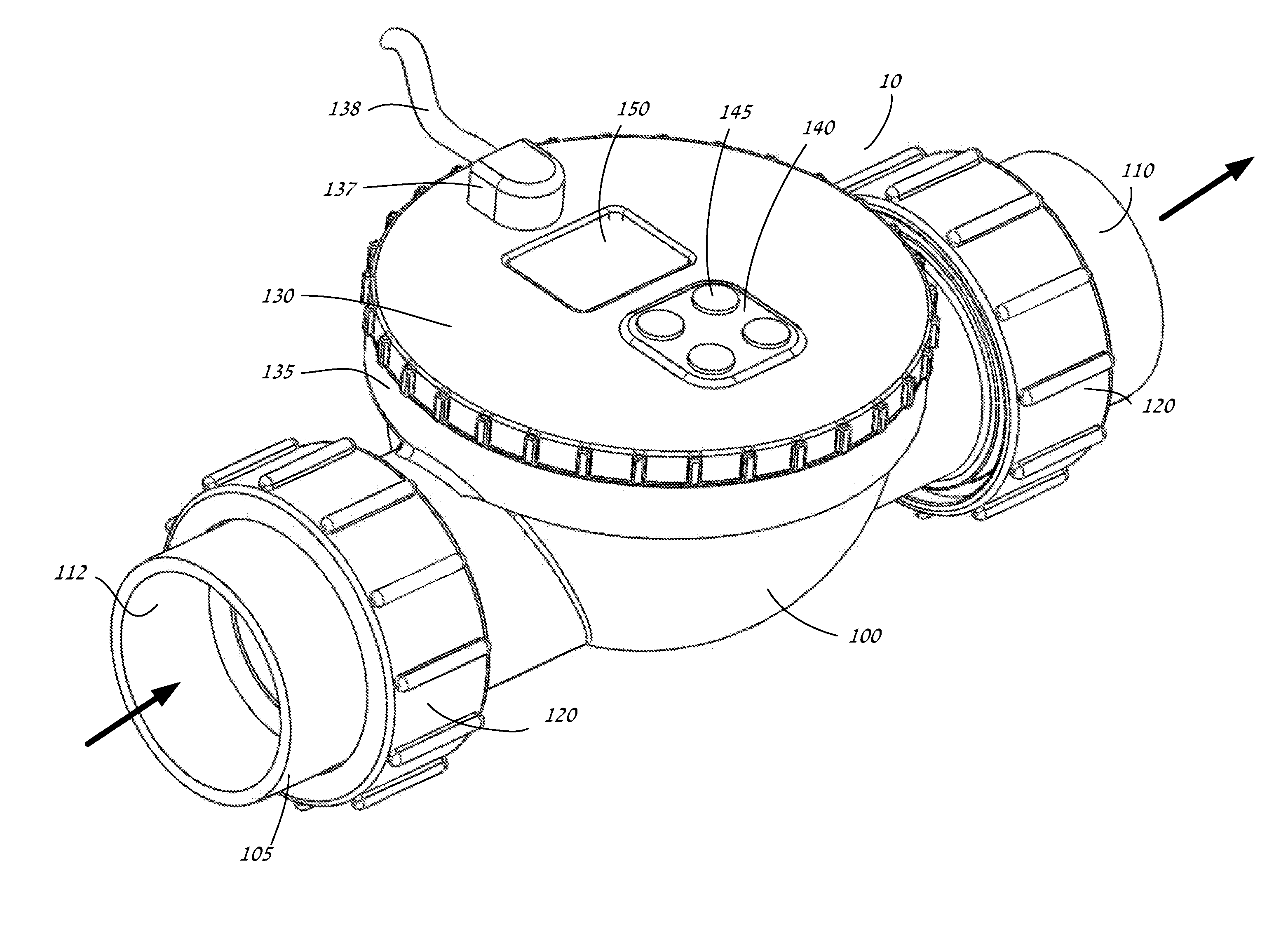
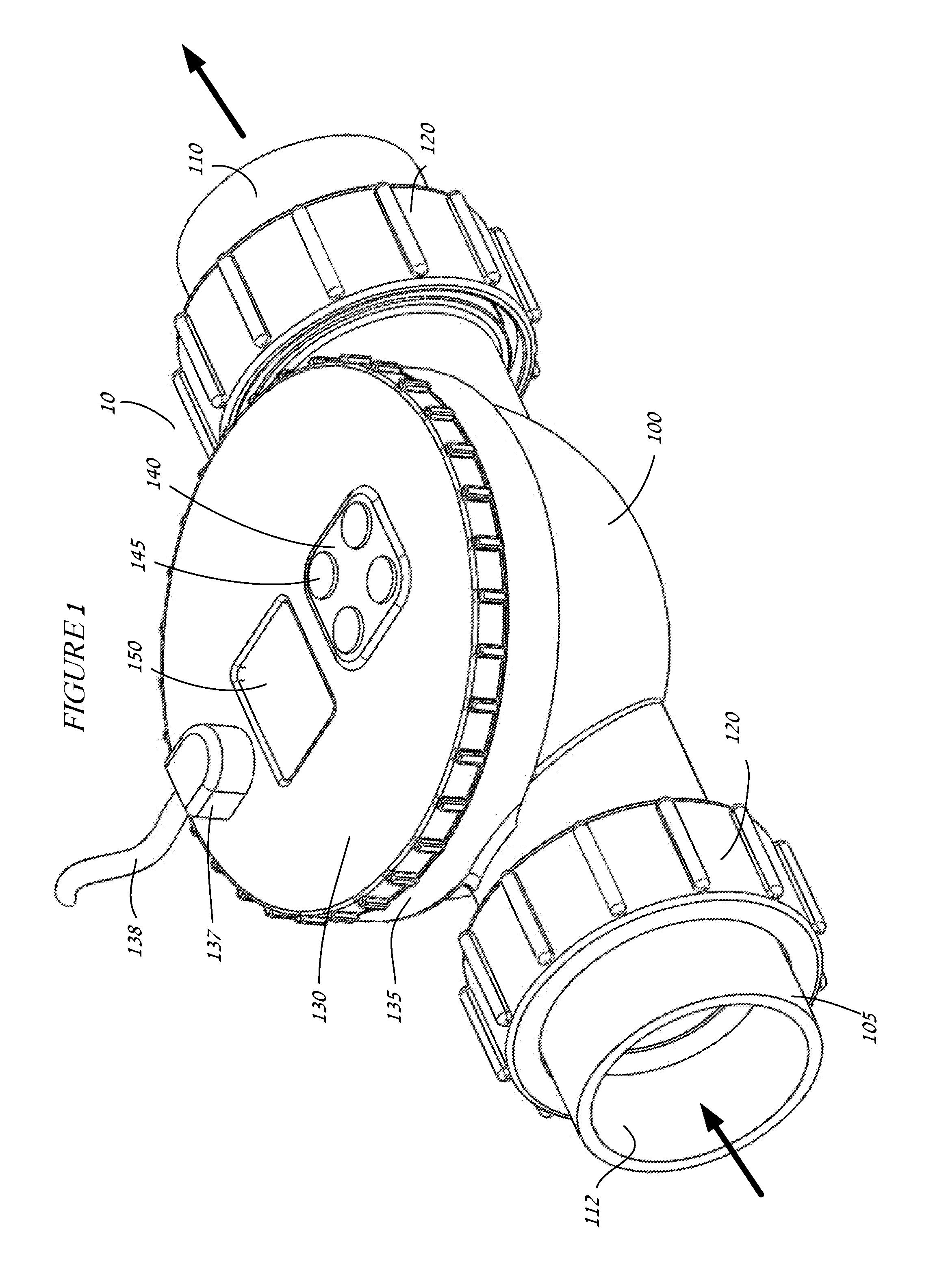
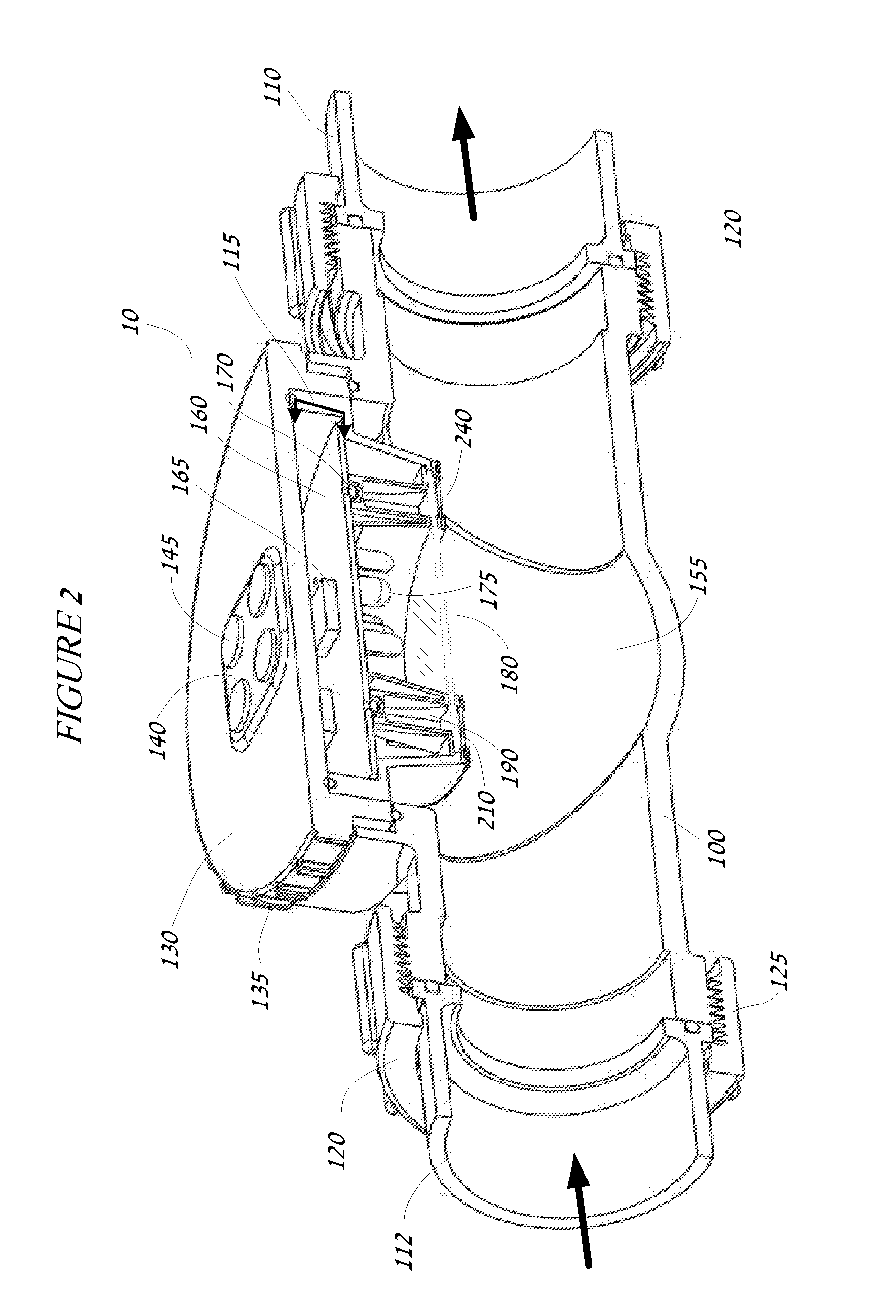
[0066]The instant invention is directed generally to a sensor system for a water treatment system having a housing that utilizes a sensor system which includes at its core a sensor target with an immobilized reagent entrapped in a molecular matrix which is capable of interacting with a reactant / analyte substance in concentration in the water of the water treatment system This entrapped reagent removes issues with corrosion, labor, maintenance, accuracy, repeatability, and lowers costs to sense parameters currently requiring a great deal of manual labor and attention. In addition, although the system can operate to sense a single parameter, the system can also be configured to sense multiple parameters. Thus, an exemplary embodiment includes elements capable of interacting and thereby sensing and reporting multiple variables for the water treatment system. The result would be a system capable of replacing a number of existing sensors, including for instance salinity, temperature, dis...


PUM

PropertyMeasurementUnit
light energyaaaaaaaaaa
energyaaaaaaaaaa
organicaaaaaaaaaa

Abstract

A sensor system in a water treatment system has a housing, controller, one or more light sources, one or more sensors and one or more targets having an immobilized reagent thereon. Light source emits light energy into the housing that is incident upon the target with the immobilized reagent and the reagent being in contact with water from the system. The immobilized reagent interacts with a reactant in the water such that the interaction changes the state of the reagent. When energy from the light source is incident on the target with the immobilized reagent the energy shows a change detectable by the sensor such that the changed energy is detectable by and collected at the sensor and data on the energy is communicated to the controller. The data is then correlated as a representation of a desired variable to be measured for the water in the water treatment system.

Description

COPYRIGHT NOTICE[0001]Portions of the disclosure of this patent document contain material that is subject to copyright protection. The copyright owner has no objection to the facsimile reproduction by anyone of the patent document or the patent disclosure, as it appears in the U.S. Patent and Trademark Office patent file or records, but otherwise reserves all copyright rights whatsoever.BACKGROUND OF THE INVENTION[0002]1. Field of the Invention[0003]The invention relates to an apparatus for sensing variables in a body of water, more specifically to a system for sensing with an immobilized reagent in a surface of a material with a matrix a reactant / component in the water of a water treatment system and sensing a change in the surface indicating a measurement of a concentration of the particular variable.[0004]2. Background of the Invention[0005]Water treatment systems require consistent monitoring of various chemical and physical properties to maintain or adjust the system for a desi...

Claims


Application Information

Patent Timeline
Patent Type & Authority Applications(United States)
IPC IPC(8): G01N33/18C12Q1/04G01N21/77
CPCG01N21/77G01N33/1893G01N33/1813G01N33/1826
Inventor REDDY, RAKESHJOHNSON, BRUCEDOYLE, KEVIN
Owner REDDY RAKESH
Why Eureka
Try Eureka