
White light source and white light source system including the same

a light source and white light technology, applied in the direction of light source semiconductor devices, sustainable buildings, light and heating equipment, etc., can solve the problems of adverse effects of white light sources on human bodies, disturbance of circadian rhythm, and disturbance of human body adverse effects, so as to achieve high reliability, effectively suppressing brightness degradation, and high reliability

Active Publication Date: 2014-09-25
SEOUL SEMICONDUCTOR
View PDF4 Cites 21 Cited by
  • Summary
  • Abstract
  • Description
  • Claims
  • Application Information

AI Technical Summary

Benefits of technology

The present invention provides a white light source that can produce the same light emission spectrum as natural light, which is good for human health. The use of multiple types of phosphor with different peak wavelengths ensures that the white light source is reliable and has a consistent color over a long period of time. Additionally, controlling the mass ratio of the phosphor can effectively prevent brightness degradation and improve the overall reliability of the white light source.

Problems solved by technology

Under the circumstances, with the popularization of the white light sources including LEDs, adverse effects of the white light sources on human bodies start to be worried about.
If a life without exposure to natural light is continued for a long period, the circadian rhythm is disturbed, and adverse effects on human bodies are worried about.

Method used


Image

  • White light source and white light source system including the same
  • White light source and white light source system including the same
  • White light source and white light source system including the same

Examples


example 1

[0109]Light emitting diodes each having a light emission peak wavelength of 400 nm were prepared as LED chips. Next, prepared was a mixture including: a europium-activated alkaline earth phosphate blue phosphor having a peak wavelength of 445 nm; a europium-activated strontium aluminate blue-green phosphor having a peak wavelength of 490 nm; a europium-activated orthosilicate green phosphor having a peak wavelength of 530 nm; a europium-activated orthosilicate yellow phosphor having a peak wavelength of 555 nm; and a europium-activated strontium sialon red phosphor having a peak wavelength of 630 nm, as phosphors that emit light while being irradiated with electromagnetic waves of 400 nm.

[0110]The average particle diameter of the respective phosphors was set to 18 μm. The respective phosphors were mixed at a ratio by weight (ratio by mass) of blue phosphor:blue-green phosphor:green phosphor:yellow phosphor:red phosphor=30:15:20:15:20, were mixed with a transparent resin (silicone re...

example 2

[0116]Light emitting diodes each having a light emission peak wavelength of 400 nm were prepared as LED chips. Next, prepared was a mixture including: a europium-activated alkaline earth phosphate blue phosphor having a peak wavelength of 445 nm; a europium-activated strontium aluminate blue-green phosphor having a peak wavelength of 490 nm; a europium-activated orthosilicate green phosphor having a peak wavelength of 530 nm; a europium-activated orthosilicate yellow phosphor having a peak wavelength of 555 nm; and a europium-activated strontium sialon red phosphor having a peak wavelength of 630 nm, as phosphors that emitted light while being irradiated with electromagnetic waves of 400 nm.

[0117]The average particle diameter of the phosphors was set to 13 μm. The respective phosphors were mixed at a ratio by weight (ratio by mass) of blue phosphor:blue-green phosphor:green phosphor:yellow phosphor:red phosphor=10:15:25:20:30, was mixed with a transparent resin (silicone resin), and...

example 3

[0122]Light emitting diodes each having a light emission peak wavelength of 400 nm were prepared as LED chips. Prepared was a mixture including: a europium-activated alkaline earth phosphate blue phosphor having a peak wavelength of 445 nm; a europium-activated strontium aluminate blue-green phosphor having a peak wavelength of 490 nm; a europium-activated orthosilicate green phosphor having a peak wavelength of 530 nm; a europium-activated orthosilicate yellow phosphor having a peak wavelength of 555 nm; and a europium-activated strontium sialon red phosphor having a peak wavelength of 630 nm, as phosphors that emitted light while being irradiated with electromagnetic waves of 400 nm.

[0123]The average particle diameter of the phosphors was set to 15 μm. The phosphors were mixed at a ratio by weight of blue-phosphor:blue-green phosphor:green phosphor:yellow phosphor:red phosphor=5:10:20:25:40, was mixed with a transparent resin (silicone resin), and was applied to the globe inner su...


PUM


Abstract

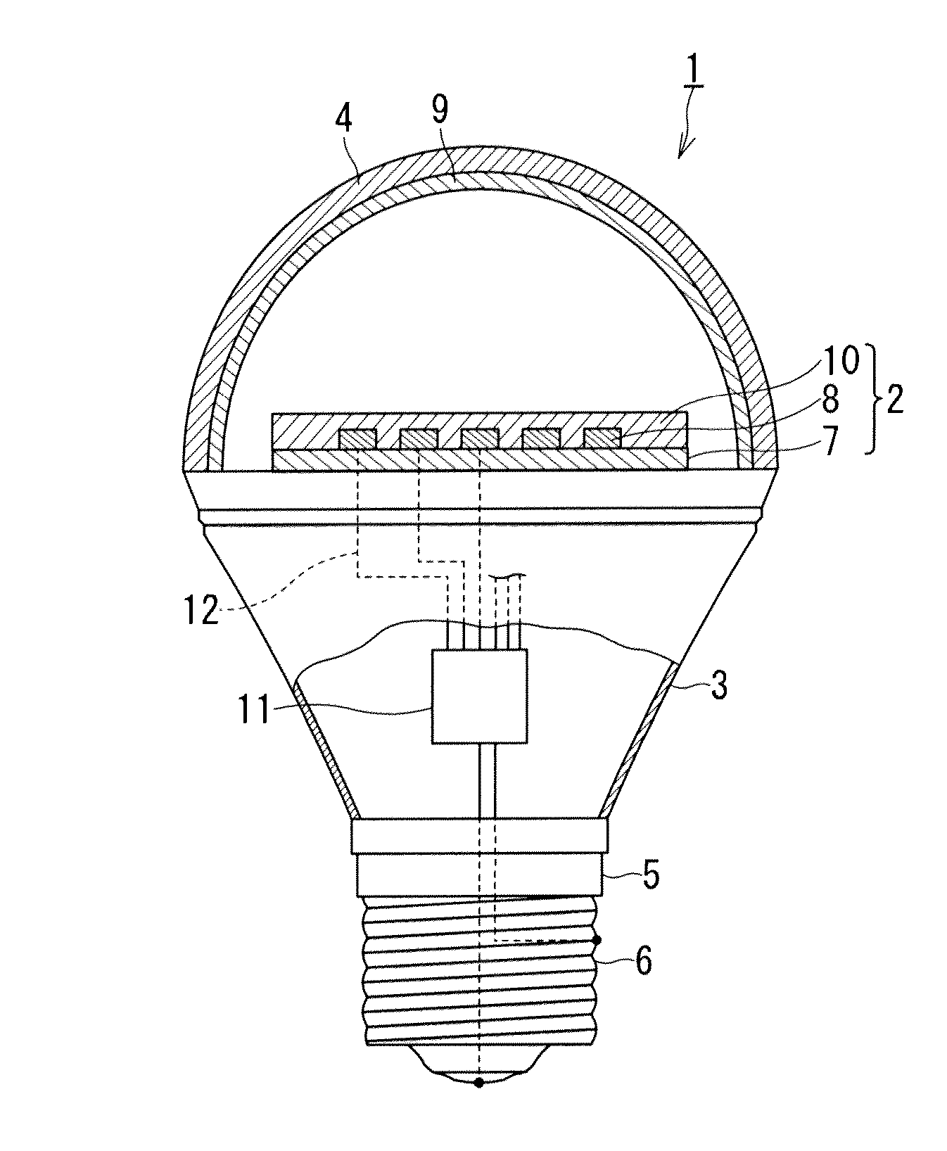
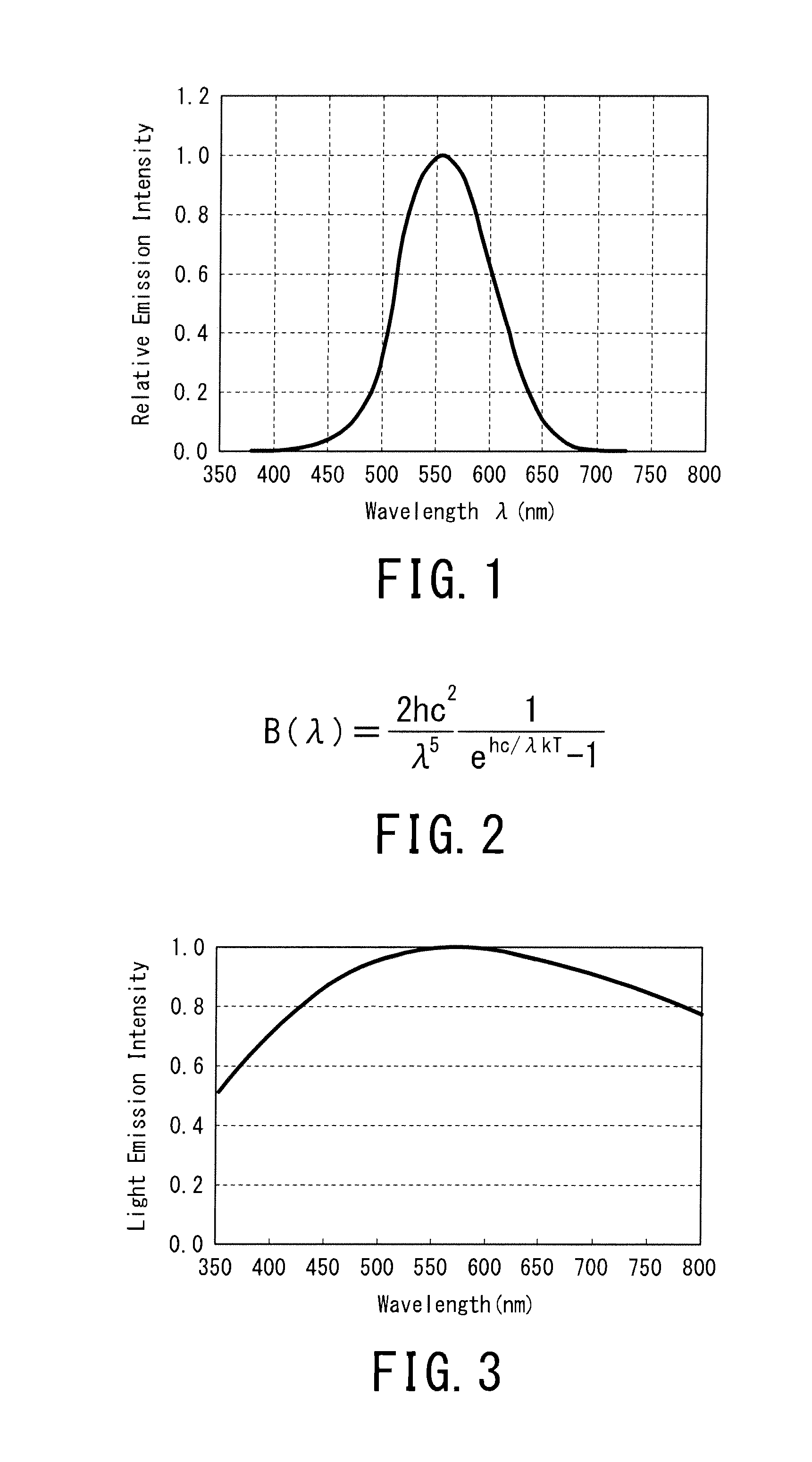
The present invention provides a white light source comprising: a light emitting diode (LED) having a light emission peak wavelength in a range of 350 or more and 420 nm or less; and a phosphor layer including four or more types of phosphors and resin, wherein the white light source satisfies a relational equation of: −0.2≦[(P(λ)×V(λ)) / (P(λmax1)×V(λmax1))−(B(λ)×V(λ)) / (B(λmax2)×V(λmax2))]≦+0.2, assuming that: a light emission spectrum of the white light source is P(λ); a light emission spectrum of black-body radiation having a same color temperature as that of the white light source is B(λ); a spectrum of a spectral luminous efficiency is V(λ); a wavelength at which P(λ)×V(λ) becomes largest is λmax1; and a wavelength at which B(λ)×V(λ) becomes largest is λmax2, and wherein an amount (difference) of chromaticity change on CIE chromaticity diagram from a time of initial lighting up of the white light source to a time after the white light source is continuously lighted up for 6000 hours is less than 0.010. According to the above white light source, there can be provided a white light source capable of reproducing the same light emission spectrum as that of natural light.

Description

TECHNICAL FIELD[0001]The present invention relates to a white light source and a white light source system including the white light source. More particularly, the present invention relates to a white light source having a light emission spectrum close to the light emission spectrum of natural light, and relates to a white light source system including the white light source.BACKGROUND ART[0002]In recent years, white light sources including light emitting diodes (LEDs) have attracted attention in terms of energy saving measures and a reduction in the amount of emitted carbon dioxide. As compared with conventional incandescent bulbs including tungsten filaments, LEDs have longer service life, and enable energy saving.[0003]As disclosed in Japanese Patent Laid-Open (Unexamined Publication) No. 10-242513 (Patent Document 1), in conventional white LEDs, YAG phosphors are excited using blue LEDs each having a light emission peak wavelength in a range of 400 to 530 nm, and the blue light ...

Claims


Application Information

Patent Timeline
IPC IPC(8): H01L33/50
CPCH01L33/504C09K11/7734C09K11/7738F21K9/13H01L33/50Y02B20/181F21K9/135F21K9/232C09K11/77348C09K11/77342Y02B20/00
Inventor YAMAKAWA, MASAHIKOSHIRAKAWA, YASUHIRO
Owner SEOUL SEMICONDUCTOR
Learn More