Liquefied gas treatment system for vessel

a gas treatment system and liquefied gas technology, applied in the direction of vessel parts, combustion air/fuel air treatment, liquid fuel feeders, etc., can solve the problems of large amount of power consumption, complicated control of the entire system, and bog burning in gas combustion units (gcus) or in atmosphere, so as to save initial installation cost and operation cost, reduce the amount of bog consumed in gcus or the like, and save energy consumption in the reliquefaction apparatus

Inactive Publication Date: 2014-10-02
DAEWOO SHIPBUILDING & MARINE ENG CO LTD
View PDF4 Cites 56 Cited by
  • Summary
  • Abstract
  • Description
  • Claims
  • Application Information

AI Technical Summary

Benefits of technology

[0030]According to the present invention, there can be provided a liquefied gas treatment system for a vessel, which can supply a high pressure gas injection engine (that is, a propulsion system) as fuel with a part of BOG compressed after pressurizing BOG discharged from a cargo tank and can newly discharge the remaining compressed BOG from a cargo tank to return it to the cargo tank by liquefying with cold energy of BOG before compression.
[0031]Therefore, according to the liquefied gas treatment system of the present invention, BOG generated from the cargo tank can be reliquefied without installing a reliquefaction apparatus consuming a large amount of energy and requiring excessive initial installation cost, thereby saving energy consumed in the reliquefaction apparatus.
[0032]In addition, according to the liquefied gas treatment system of the present invention, all BOG generated during the transportation of cargo (that is, LNG) in the LNG carrier can be used as the fuel of the engine, or may be rel...

Problems solved by technology

The generated natural gas may increase the inside pressure of the cargo tank and accelerate the flow of the natural gas due to the rocking of the vessel, causing structural problems.
Therefore, when an amount of fuel necessary for an engine is smaller than a generation amount of BOG, there is a problem that BOG is burnt in a gas combustion unit (GCU) or ...

Method used


Image

  • Liquefied gas treatment system for vessel
  • Liquefied gas treatment system for vessel
  • Liquefied gas treatment system for vessel

Examples


first embodiment

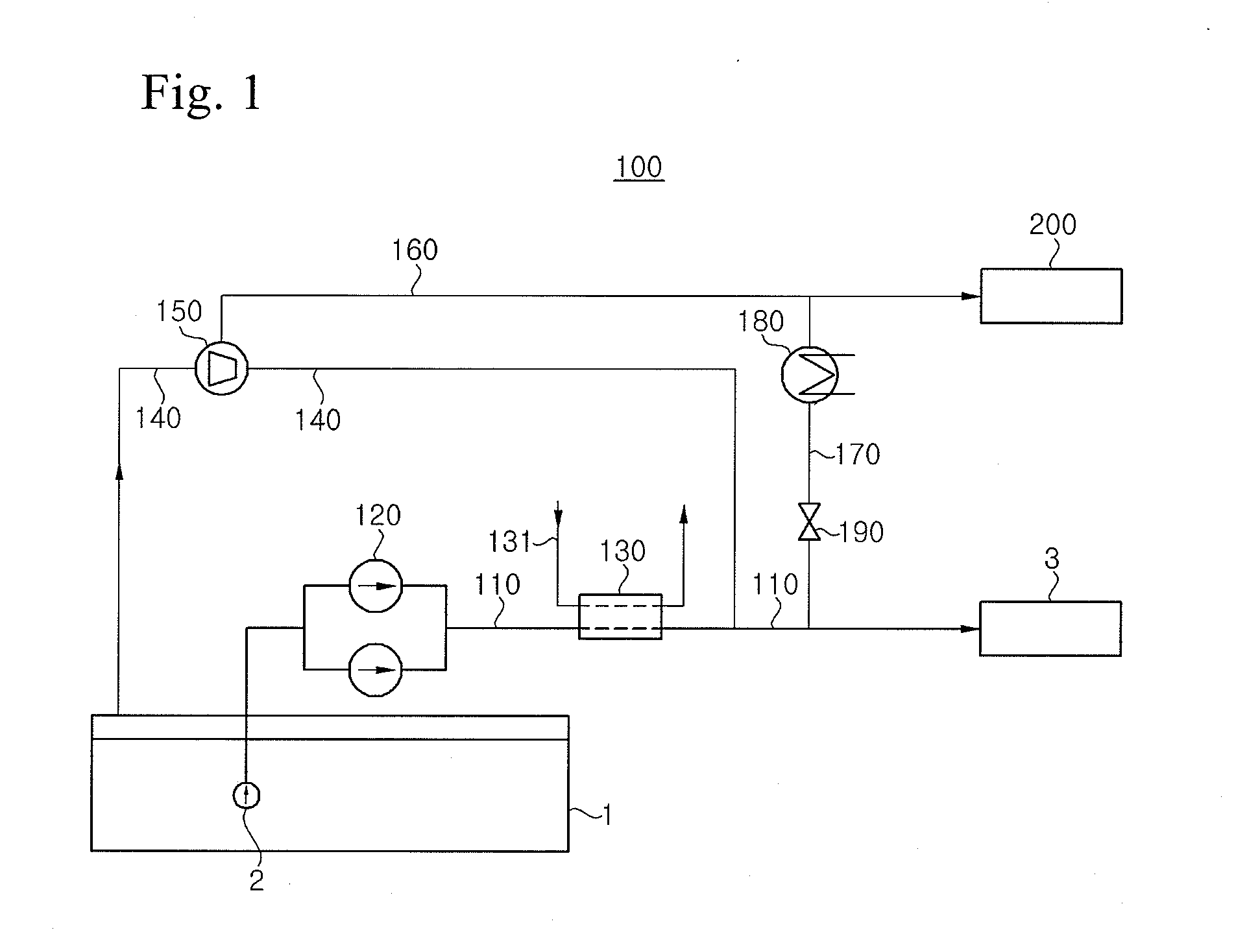
[0055]FIG. 1 is a configuration diagram illustrating a liquefied gas treatment system for a vessel according to the present invention. The liquefied gas treatment system of the present embodiment may be applied to an LNG carrier equipped with an ME-GI engine as a main propulsion engine (that is, propulsion means using LNG as fuel).

[0056]Referring to FIG. 1, the liquefied gas treatment system 100 according to the present embodiment includes a fuel supply line 110 and a BOG line 140. The fuel supply line 110 is configured to provide a passage for transferring LNG from a cargo tank 1 to a main engine 3 as a propulsion system. The BOG line 140 is configured to provide a passage for transferring BOG generated from the cargo tank 1 to the main engine 3. In addition, the liquefied gas treatment system 100 using BOG according to the present embodiment supplies LNG to the main engine 3 as fuel through the fuel supply line 110 by an LNG pump 120 and an LNG vaporizer 130, supplies BOG to the m...

second embodiment

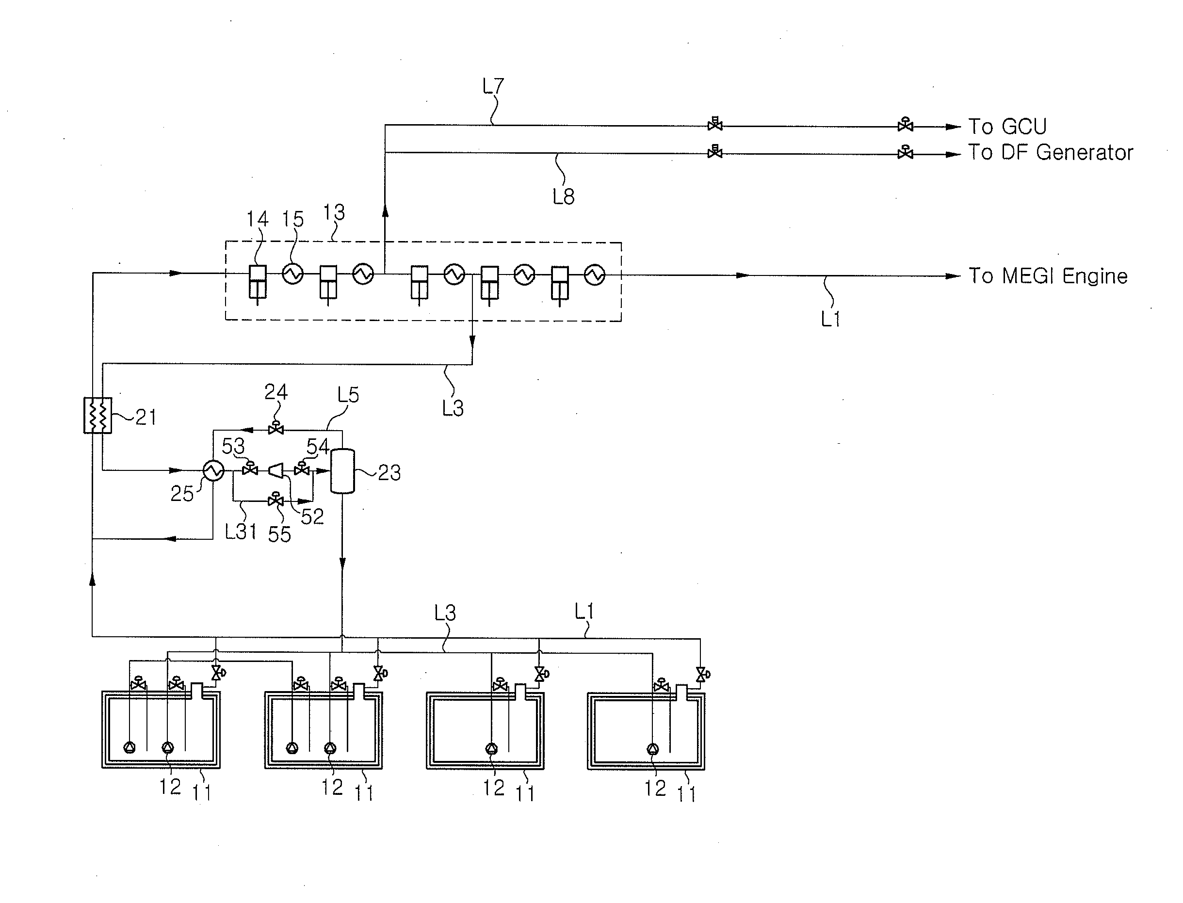
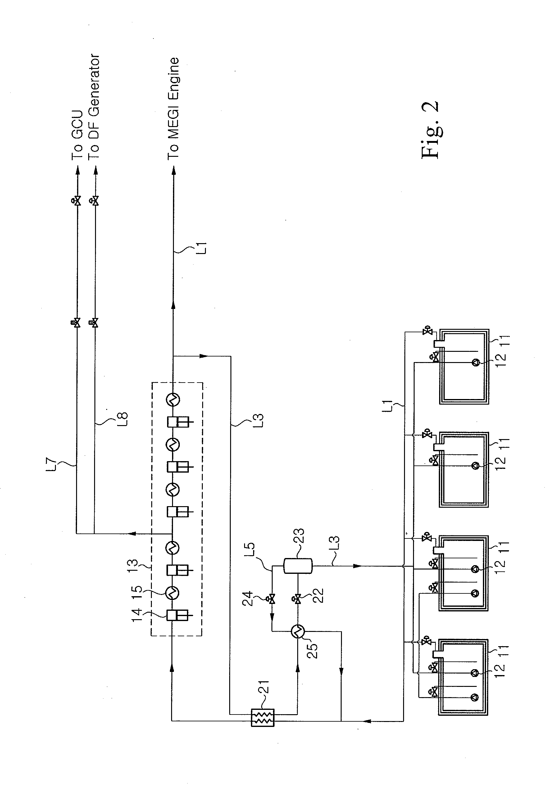
[0070]FIG. 2 is a schematic configuration diagram illustrating a liquefied gas treatment system for a vessel according to the present invention.

[0071]Although FIG. 2 illustrates an example in which the liquefied gas treatment system of the present invention is applied to an LNG carrier equipped with a high pressure natural gas injection engine capable of using natural gas as fuel (that is, propulsion means using LNG as fuel), the liquefied gas treatment system of the present invention can also be applied to any type of vessels (LNG carrier, LNG RV, and the like) and marine plants (LNG FPSO, LNG FSRU, BMPP, and the like), in which a liquefied gas cargo tank is installed.

[0072]In the liquefied gas treatment system for the vessel according to the second embodiment of the present invention, NBOG generated and discharged from a cargo tank 11 storing liquefied gas is transferred along a BOG supply line L1, is compressed in a compressor 13, and is then supplied to the high pressure natural...

third embodiment

[0092]FIG. 5 is a schematic configuration diagram illustrating a liquefied gas treatment system for a vessel according to the present invention.

[0093]The liquefied gas treatment system according to the third embodiment differs from the liquefied gas treatment system according to the second embodiment in that LNG can be used after forcible vaporization when an amount of BOG necessary for the ME-GI engine or the DF generator is larger than an amount of BOG generated naturally in the cargo tank 11. Hereinafter, only a difference from the liquefied gas treatment system of the second embodiment will be described in more detail. In addition, the same reference numerals are assigned to the same elements as those of the second embodiment, and a detailed description thereof will be omitted.

[0094]The liquefied gas treatment system for the vessel according to the third embodiment of the present invention is identical to that according to the second embodiment in that NBOG generated and dischar...


PUM


Abstract

A liquefied gas treatment system includes: a first stream of boil-off gas, which is generated from the liquefied natural gas in the cargo tank and is discharged from the cargo tank; a second stream of the boil-off gas, which is supplied as fuel to the engine in the first stream; and a third stream of the boil-off gas, which is not supplied to the engine in the first stream. The first stream is compressed in a compressor and is then branched into the second stream and the third stream. The third stream is liquefied by exchanging heat with the first stream in a heat exchanger, so that the boil-off gas is treated without employing a reliquefaction apparatus using a separate refrigerant.

Description

TECHNICAL FIELD[0001]The present invention relates to a liquefied gas treatment system for a vessel.BACKGROUND ART[0002]Recently, the consumption of liquefied gas, such as liquefied natural gas (LNG) or liquefied petroleum gas (LPG), has been rapidly increasing throughout the world. Liquefied gas is transported in a gas state through onshore or offshore gas pipelines, or is transported to a remote consumption place while being stored in a liquefied state inside a liquefied gas carrier. Liquefied gas, such as LNG or LPG, is obtained by cooling natural gas or petroleum gas to a cryogenic temperature (in the case of LNG, about −163° C.). Since the volume of liquefied gas is considerably reduced as compared to a gas state, liquefied gas is very suitable for a long-distance marine transportation.[0003]A liquefied gas carrier such as an LNG carrier is designed to load liquefied gas, sail across the sea, and unload the liquefied gas at an onshore consumption place. To this end, the liquefi...

Claims


Application Information

Patent Timeline
IPC IPC(8): B63B25/16F02M21/02F25J1/00F17C9/02F17C13/08
CPCB63B25/16F17C9/02F17C2221/033F25J1/0025F02M21/0215F17C13/082B63H21/38F02M21/02F17C2201/0157F17C2201/052F17C2223/0161F17C2223/033F17C2265/034F17C2265/037F17C2265/066F17C2270/0107F02M21/0221F25J1/004F25J1/0042F25J1/0202F25J1/023F25J1/0277F02M21/0212F02M21/023F02M21/0245F02M21/0248F02M21/0287F02M31/16Y02T10/12Y02T10/30Y02T70/50Y02T90/40B63H21/12F02D19/06F02M37/00F02M37/04F02M21/0209B63B25/08F17C7/02B63B25/14F17C1/002B63H21/00F17C7/04
Inventor LEE, JOON CHAECHOI, DONG KYUMOON, YOUNG SIKJUNG, SEUNG KYOJUNG, JEHEONKIM, NAM SOO
Owner DAEWOO SHIPBUILDING & MARINE ENG CO LTD
Why Eureka
Try Eureka