Technologically, however, the power systems have not kept major improvements as occurred in the fields of
electronics,
telecommunications and computing, carrying essentially the same ideas, forms and the same original problems.
Despite the large capillarity, because the distribution network has to reach every individual
residence, the information collected and stored by utilities are relatively sparse.
This is mainly due to the lack of low cost and reliable communication from the many end branches of the
system.
As an example of the difficulties imposed by the lack of information on the
current distribution system, in case of a power outage at a
client, the
energy distribution company, in almost all cases, has no way to detect the fault unless the client reports the failure, even if the fault is in the distribution network itself.
Also, in cases of power
cut-off for nonpayment and reconnection after
payment settlement, the company has to move a vehicle to the client installation to perform these functions.
Considering that distribution companies have thousands and even millions of clients, this implies that the costs involved in these operations are quite high.
Although there are several technologies available, the
biggest problem for its implementation is the huge investment involved, which would only be amortized over several years.
Apart from modernization initiatives, a chronic problem of
distribution networks is related to energy losses, which are classified in technical losses and commercial losses.
Commercial losses are related to the process of commercialization of energy and involve errors in measurement and consumption reading, errors in the billing process and especially frauds and energy thefts.
Thefts are characterized by illegal connections that divert the energy so that it is not registered by the meter.
Commercial losses not only represent lost revenue for utilities, but also a huge loss to society because there is no related tax collection and part of the prejudice is transferred to the
energy rate of regular customers, burdening businesses and the
population.
According to estimates made by Brazilian National
Electric Energy Agency (ANEEL), losses are responsible for about 15% of the total active power purchased by distribution companies, representing a huge loss to society.
The most common types of fraud include a wide range of tampering with consumption measurement, such as waging the meter disk via external agent, breaking the meter seal for tamper with the mechanism or electro-electronic part and various other methods often very creative, making their detection difficult by the energy
distributor.
In fact, the
energy distribution companies develop a series of actions aimed at reducing these unlawful practices of
electricity subtraction and, despite all efforts, it is clear that the solutions currently in use have proved to be ineffective and, to minimize the possibility of fraud and energy theft, the techniques and equipment need to be improved.
Analyzing the various documents existing on the subject, the difficulty is perceived.
None of these solutions, however, prevents the deviation that is made directly from the distribution network, featuring the power theft.
This procedure is not effective because the client installation can be easily changed by placing an insulation device, as a
contactor, after the meter and before the client load, which makes the developed
voltage measurement technique innocuous.
However, the use of this cable is restricted to client's service drop, between the
utility pole and the client measurement box, due to the cost of the cable and its limited current capacity.
Thus, even though its use
efficacy in service drops, the problems of direct connection to the secondary network and tampering measurement still remain.
These approaches have two major problems.
A filter that is not authorized by the company could be easily assembled or stolen from another client installation.
The second problem, in the case of making energy unfit for consumption, is that purely resistive devices such as showers, would be unaffected by the superimposed
DC voltage, functioning satisfactorily.
This device detects the energy theft on the service drop, in other words, between the pole and the meter, but does not detect secondary network energy theft or metering fraud.
In addition, customers with higher loads may claim that the electrical losses in service drop, being responsibility of the power company, were being charged directly from him (client) since the measurement occurs before the service drop, which will certainly bring legal and billing settlement issues for utility companies.
This approach is only feasible for a very small number of customers and presents several problems, such as:Theft or fraud would be detected only if there is consumption at the time of measurement;For a real number of customers in a distribution company (thousands / millions) the procedure would be unfeasible because it would require a very long time to test all clients;The distribution company would have their service continuity index worsened, which could result in penalties imposed by the energy agency.
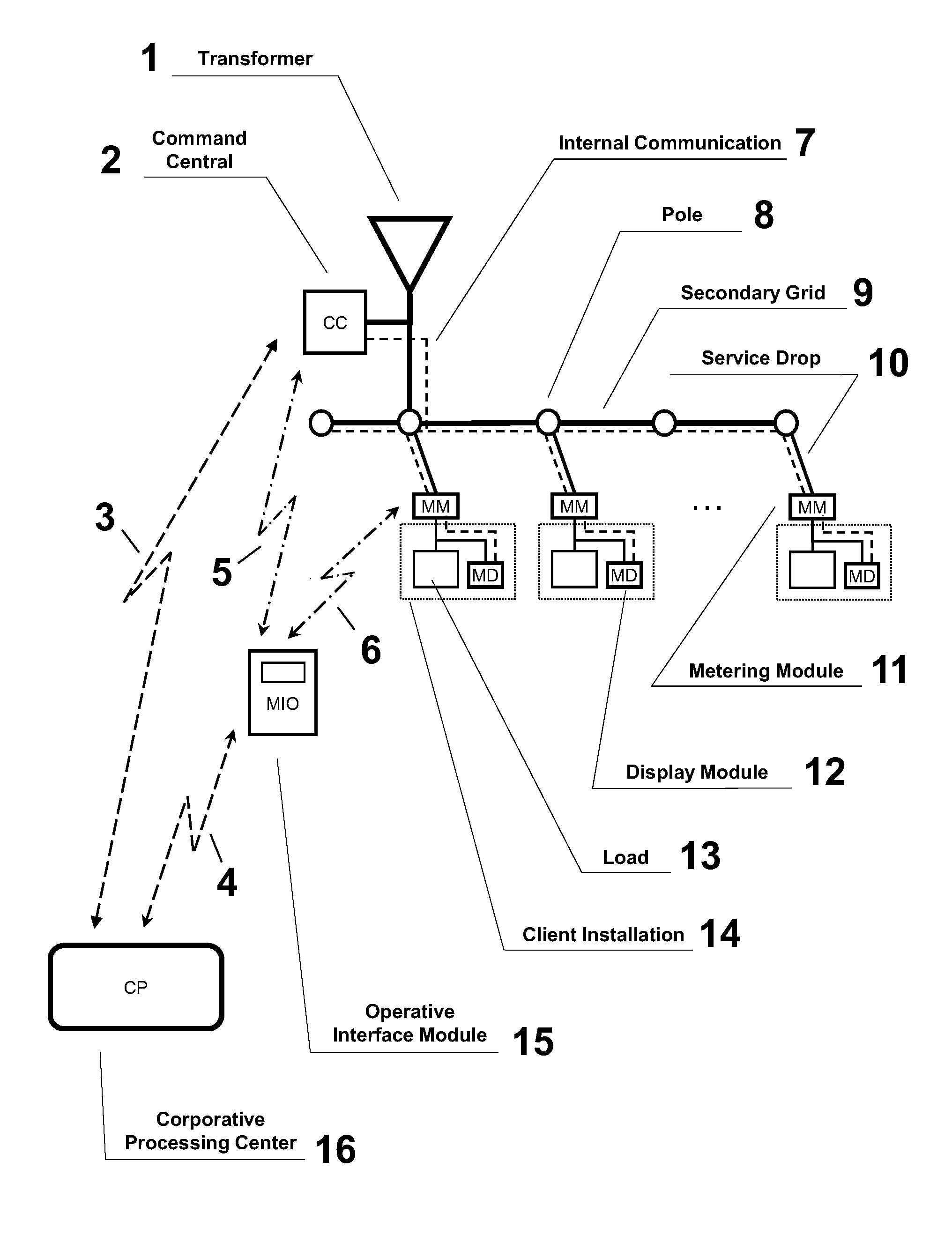
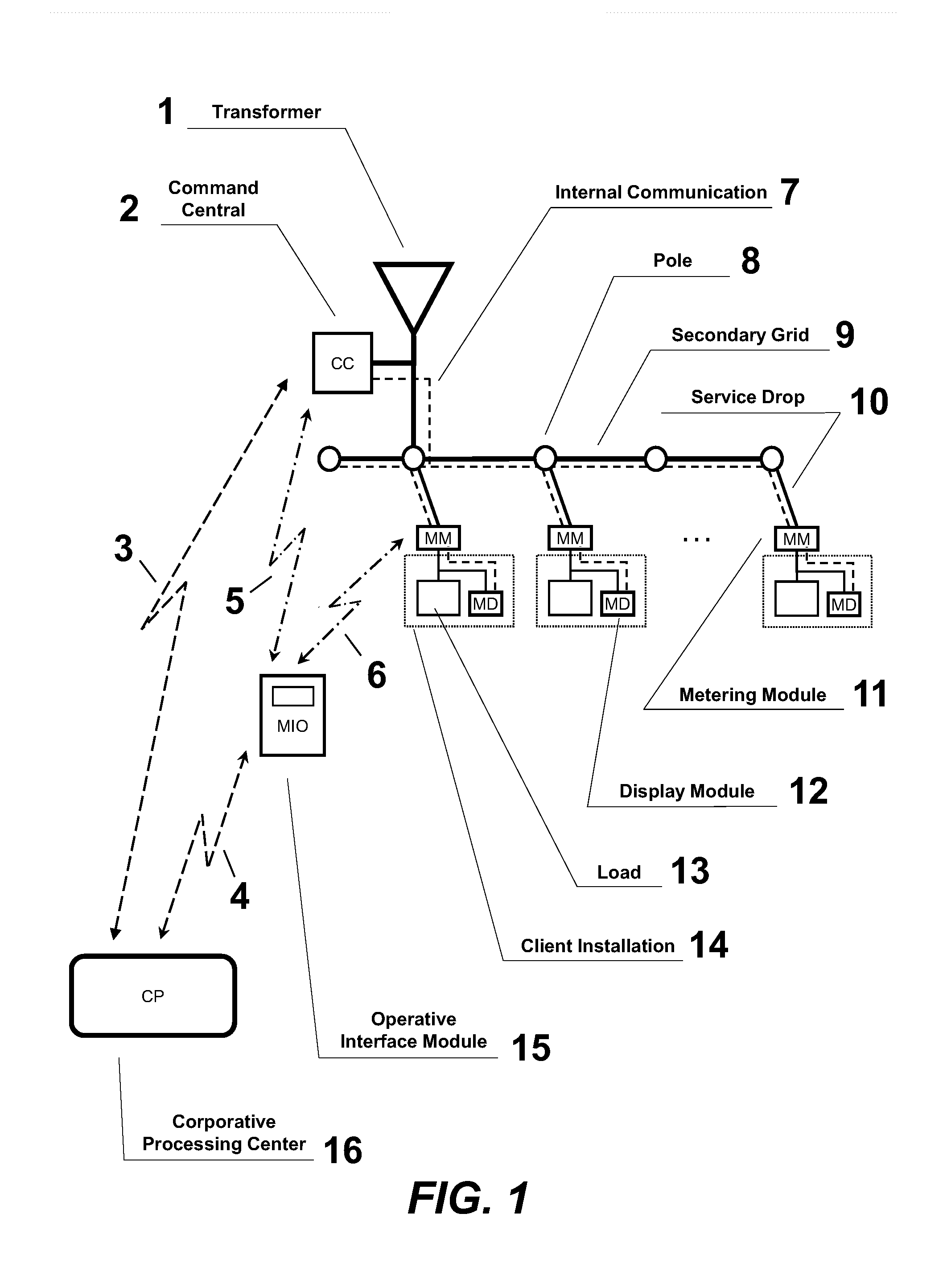
Similar methods are used for communication between the meters, intermediate units and
central processing unit, however, the measurements are not made in order to obtain a
phasor sum to detect abnormalities in the circuit, mainly because of the intermediate units do not have any capability of measuring or checking electrical parameters.
Furthermore, they do not address the need for safe procedures for network setup operations such as installation, substitution and removal of devices.
It is relevant to note that, in case of communication failure, these systems do not provide alternative mode of operation.
Despite of this necessary time, observed in all real implementations of this technique, the article claims to allow “the detection, location and quantification of losses, almost instantly,” what does not appear feasible in practice.
Furthermore, this technique is not suitable to detect differences caused by the public lighting loads, present in almost all
low voltage urban circuits, and neither the energy losses in the circuit, making the detection coarse and inaccurate, allowing to detect only the cases where there is massive fraud or theft.
Another important aspect is that there is no security procedure to avoid the replacement of irregular meters adulterated in UD's, making the energies sum being consistent with the measurement at UT (except losses and street lights, as quoted), making frauds undetectable.
The system described presents several problems related to mitigating fraud losses and energy theft when related to distribution companies' networks, because:Does not contemplate or include public lighting charges;Allows installation of tampered sensors or even new illegal sensors without control over them because there is no security procedures for installation, removal and replacement of sensors;It is applicable only to internal networks and three-phase loads of consumers (typically industrials), while the
distribution networks can be mono- , bi- and three-phasic and come with one, two or three phases loads;Uses
synchronizing technique by GPS (
Global Positioning System) in each sensor to establish the necessary
phasor measurements, making the total system cost very high to be feasible to the typical
distribution networks;Allows measurement of part or subset of the monitored circuit that precludes the detection of fraud and theft on the network, because there is no way to directly compare the measured values of the subset of sensors with the centralized measurement, which covers all the circuits.

