Composite Fuel Rod Cladding

a fuel rod and composite technology, applied in the field of composite fuel rod cladding and nuclear fuel assembly, can solve the problems of reducing the mechanical properties bending of the original straight fuel assembly, and different expansion of the material, so as to enhance the structural integrity of the fuel rod cladding, reduce friction between the fibers, and add strength

Active Publication Date: 2014-10-16
AREVA INC
View PDF2 Cites 6 Cited by
  • Summary
  • Abstract
  • Description
  • Claims
  • Application Information

AI Technical Summary

Benefits of technology

[0012]A fuel rod of the present invention includes an elongate hollow cladding, configured to retain a nuclear fuel therein. The nuclear fuel is typically provided in fuel pellets made of fissile material including uranium, plutonium, or a mixture thereof. The fuel cladding is formed of a tube made of a ceramic material, with silicon carbide being a preferred ceramic. The ceramic material is chosen such that it can withstand temperatures and radiation typical of an operating nuclear reactor without deformation.
[0013]The fuel cladding further includes one or more fiber layers positioned or spun about the tube. Each fiber layer is also formed of at least one fiber of a ceramic material, and preferably of the same material as the tube. The fiber layers provide added strength and enhance the structural integrity of the fuel cladding. The fuel cladding may further include a residual substance such as boron or graphite to reduce friction between the fibers. This lubricating residual substance can be an integral part of the fibers themselves, or an added substance separate from the fiber layers. The mass of the residual substance preferably does not exceed 8% of a total mass of the fibers.

Problems solved by technology

In spite of the favorable properties of the zirconium alloys, fuel rod claddings manufactured from a zirconium alloy are affected by the environment in the reactor (heat, radiation, chemistry environment, amount of deposition, and location of deposition on fuel rods) such that the material expands differently, or in a non-uniform manner.
The expansion of the zirconium alloy arises anisotropically, which results in an originally straight fuel assembly becoming bent during its life in a number of directions away from its original longitudinal axis.
Hydrogen pick up is concentrated in the form of hydrides in the zirconium alloy, which, in addition to the permanent deformation, also results in a weakening of the mechanical properties of the fuel rod cladding.
Due to the fuel assembly's great length, even a small inhomogeneous permanent deformation of the fuel rods may create a large bending of the fuel assembly.
Any permanent deformation of a fuel assembly results in difficulties in movement of the control elements since there could be, for example in BWRs, frictional contact between the control blades and fuel channels resulting in “slow to settle” or totally inactive control blades.
This condition would allow dissipation of radioactive materials in the melt resulting during a beyond conceivable limits accident inside the reactor vessel, and create higher impacts to the environment and to the cost and duration of recovery after such an accident.

Method used


Image

  • Composite Fuel Rod Cladding
  • Composite Fuel Rod Cladding
  • Composite Fuel Rod Cladding

Examples


Embodiment Construction

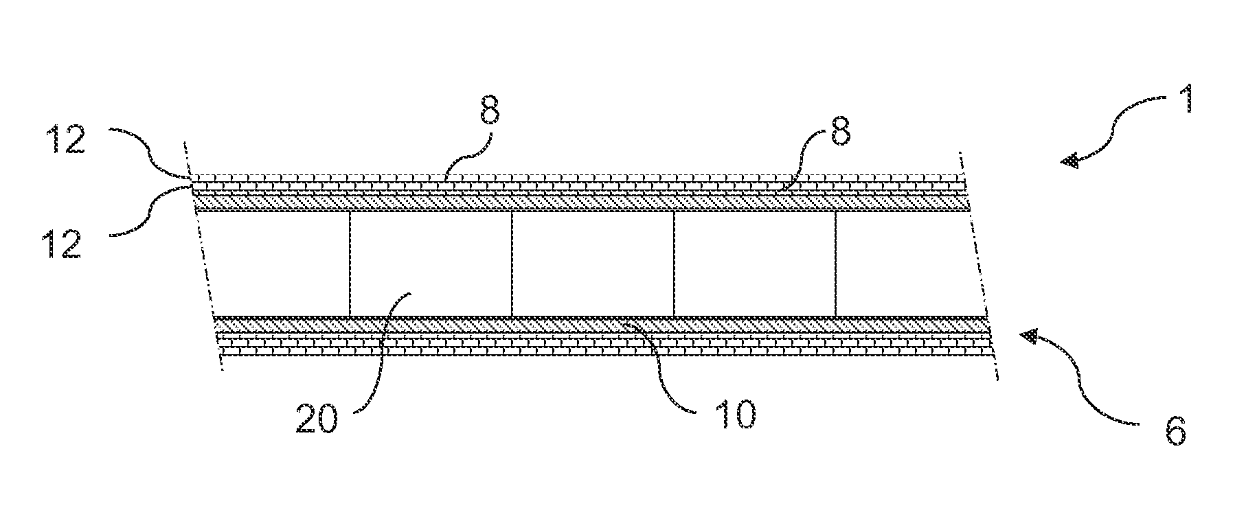
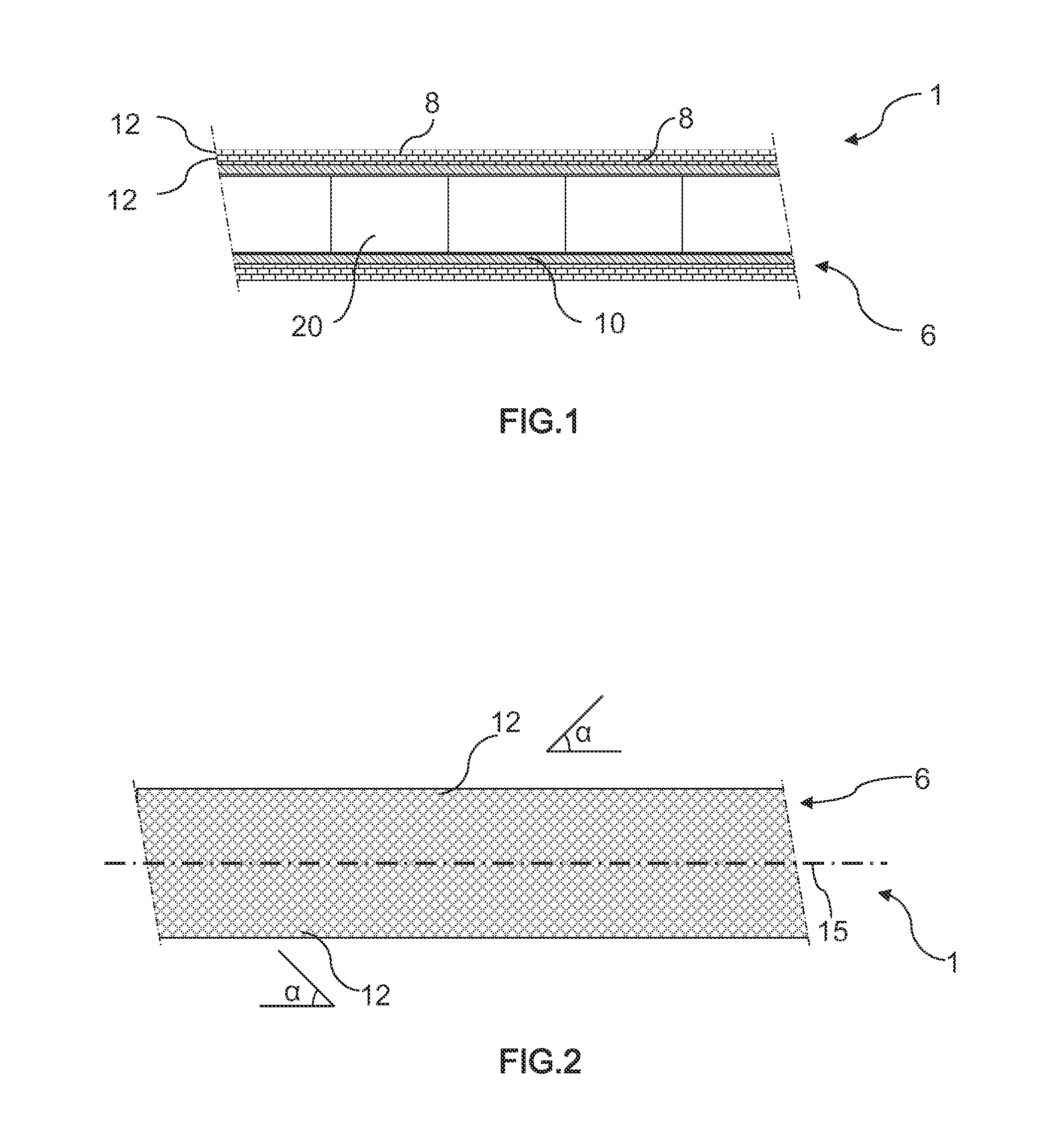
[0021]The present invention provides nuclear fuel rods 1 formed of a composite ceramic cladding 6 configured to retain nuclear fuel pellets 20 therein in a known manner. Silicon carbide (SiC) is a preferred ceramic material. As illustrated in FIG. 1, the composite ceramic cladding 6 comprises a tube 10 covered by a number of layers 12 of fibers 8 spun around the tube 10. Preferably, the fiber layers 12 are placed about the tube 10 in varying directions, enhancing the strength of the fuel rod 1. For example, as shown in FIG. 2, the fiber layers 12 may be arranged iii a direction non-parallel with the fuel rod longitudinal axis 15 at an angle α that is between approximately 30° to 70° relative the longitudinal axis 15. (It should be noted that for the sake of clarity, only a single fiber 8 per fiber layer 12 is illustrated in FIG. 2.) Subsequent fiber layers 12 preferably are placed atop the previously placed fiber layer(s) 12 such that the additional fiber layer 12 is non-parallel to...


PUM

PropertyMeasurementUnit
aspect ratioaaaaaaaaaa
relative angleaaaaaaaaaa
angleaaaaaaaaaa

Abstract

A fuel rod for a nuclear fission reactor is disclosed and claimed. The fuel rod includes an elongate hollow cladding configured to retain a nuclear fuel therein. The cladding includes an elongate hollow tube. Fiber layers are positioned around the outside surface of the tube or within the tube forming an integral part thereof. Both the tube and the fibers are formed of a ceramic material. A fuel assembly including a plurality of such fuel rods is also disclosed and claimed.

Description

CROSS-REFERENCE TO RELATED APPLICATIONS[0001]This patent application claims the benefit of U.S. Provisional Patent Application No. 61 / 810,618 filed on Apr. 10, 2013, which is incorporated herein by reference in its entirety.BACKGROUND OF THE INVENTION[0002]1. Field of the Invention[0003]The present invention relates to nuclear fuel assemblies for use in a nuclear fission reactor, and, more particularly, the present invention relates to nuclear fuel assemblies with nuclear fuel rods formed with a cladding of a composite ceramic material.[0004]2. Description of the Related Art[0005]During operation of a nuclear fission reactor, the function of the fuel rods within a fuel assembly is to allow transmission of the heat resulting from the fission reaction inside the fuel pellets mounted within the fuel rod while separating the radioactive material from the streaming cooling fluid, which in light water reactors is water. A nuclear fuel rod typically includes a cladding tube that houses a. ...

Claims


Application Information

Patent Timeline
Patent Type & Authority Applications(United States)
IPC IPC(8): G21C3/07
CPCG21C3/07C04B35/806B32B18/00C04B2235/5244C04B2237/365C04B2237/38Y02E30/30
Inventor POP, MIHAI G. M.
Owner AREVA INC
Why Eureka
Try Eureka