Method Of Controlling A Dynamic Physical System That Exhibits A Chaotic Behaviour

Active Publication Date: 2014-10-16
OXFORD BROOKES UNIVERSITY
View PDF11 Cites 5 Cited by
  • Summary
  • Abstract
  • Description
  • Claims
  • Application Information

AI Technical Summary

Benefits of technology

[0034]Alternatively, the control term may be the volumetric flow-rate {dot over (v)}s of the conditioned supply air. In that case, the rate control function may be:
[0035]In the first aspect of the invention, the dynamic physical system may be a semiconductor laser system. The semiconductor laser system may be of a non-linear laser ring cavity type. Advantageously, the control term may be the amo

Problems solved by technology

Chaotic dynamic physical systems are dynamic physical systems that exhibit behaviour that is deterministic in a mathematical sense (the behaviour is precisely determined by the state at any particular time), but nevertheless unpredictable over time due to the sensitivity of the system on the state.
Due to this unpredictability, when attempting to control a dynamic physical system it is generally considered undesirable to allow it to enter a chaotic state

Method used


Image

  • Method Of Controlling A Dynamic Physical System That Exhibits A Chaotic Behaviour
  • Method Of Controlling A Dynamic Physical System That Exhibits A Chaotic Behaviour
  • Method Of Controlling A Dynamic Physical System That Exhibits A Chaotic Behaviour

Examples


example 1

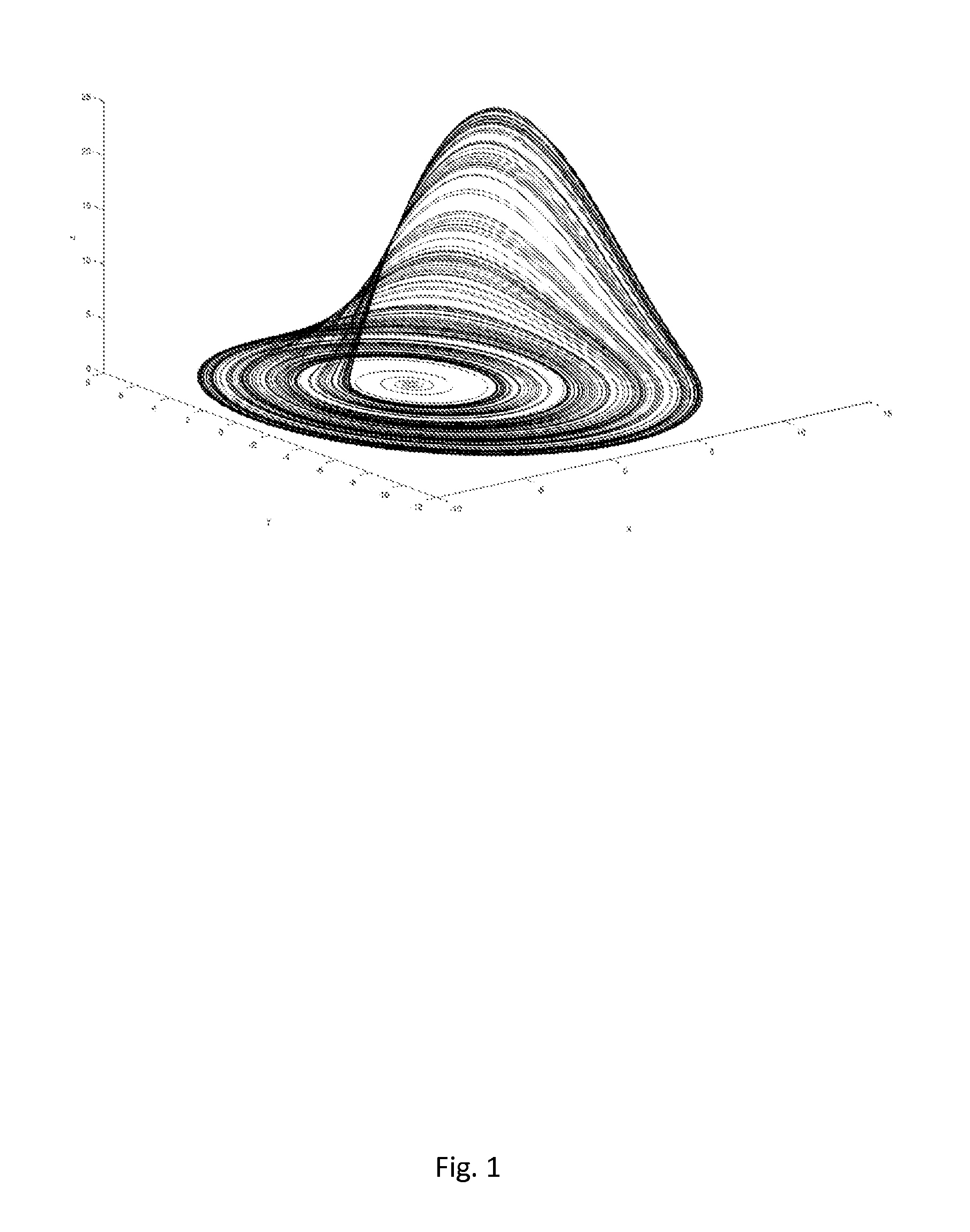
[0087]An embodiment in which the method of the invention is applied to an example system is now described. The system is the Rössler system, a well-known dynamic physical system that exhibits chaotic behaviour, which is defined by the following rate equations:

xt=-(y+z)yt=x+yαzt=βα+(zx)-(γz)

[0088]Considering third rate equation for the variable z, the growth of the variable z is given by the terms zx and β / α, and so the control term is taken to be the term zx (as the constant term β / α cannot be varied). The proportion of each variable in the control term, to the growth rate is given by the quotients:

qx=xx+μxandqz=zz+μz

where ux and uz are constants.

[0089]These quotients are then used to derive a rate control function σ for the variable z, as follows:

σ(x,z)=feξ,qxqz=fe{ξ(xz)(xz+x+z+μ)}

where f and ξ are scalars as discussed above. (The scalar f is used to set the overall level of control applied to the system, while the scalar ξ is used to stabilise the system to different orbits.)

[0090...

example 2

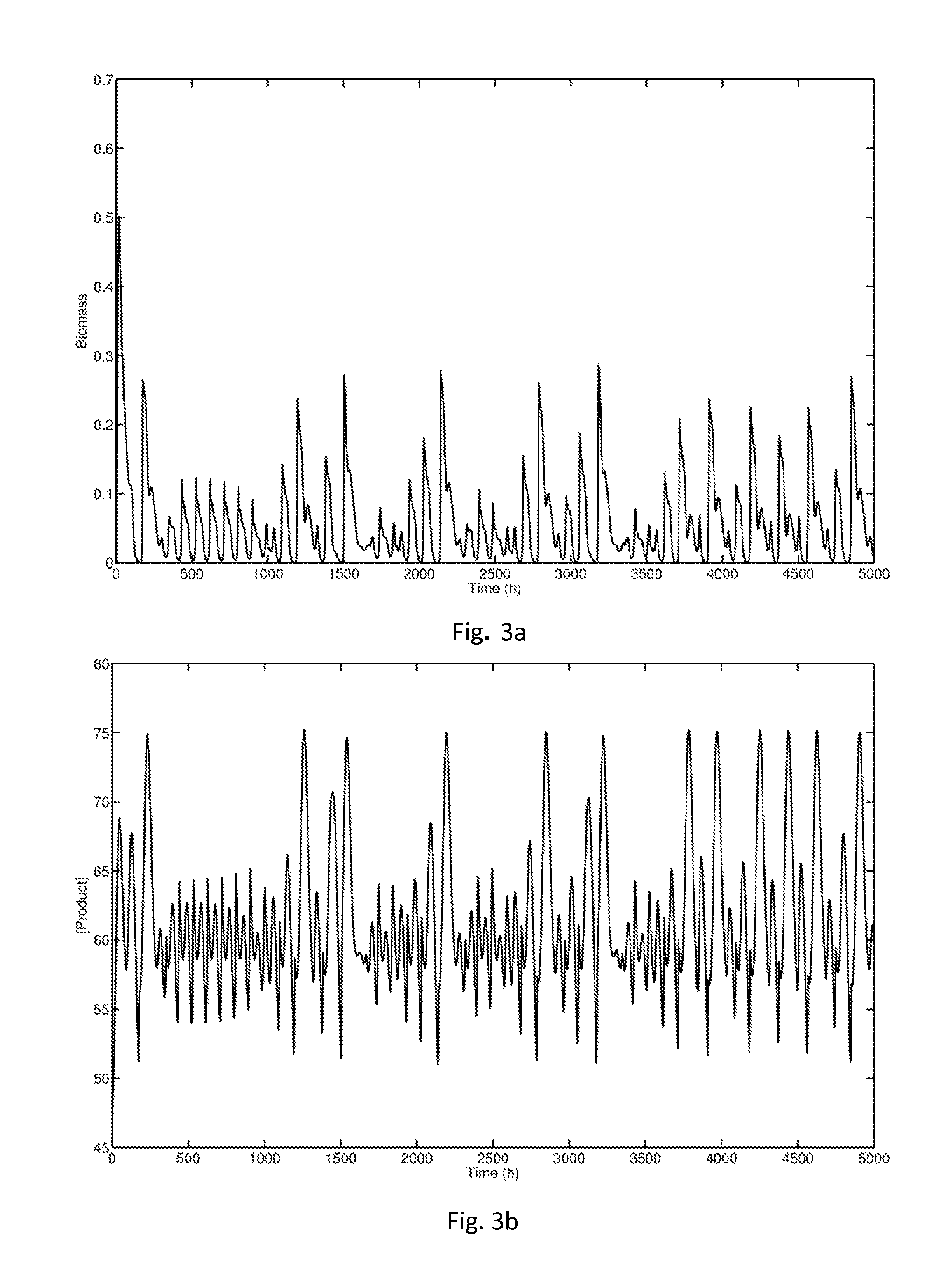
[0092]An embodiment in which the method of the invention is applied to a bioreactor is now described; that is, a biochemical process to manufacture a desired product by means of a biochemical reaction. Bioreactors and generic models thereof are described in Michael A. Henson. Exploiting cellular biology to manufacture high-value products. IEEE Control Systems Magazine, pages 54-62, August 2006.

[0093]In particular, the method of the invention as applied to a bioethanol fermentor is now described. A bioethanol fermentor is a system that produces ethanol by fermenting biomass such as waste agricultural material (sugar, fruit, grains, potatoes etc.). The biomass is fermented using a microorganism such as Zymomonas mobilis. A bioethanol fermentor is described in I. M. Jöbses, G. T. Egberts, K. C. Luyben, and J. A. Roels, “Fermentation kinetics of Zymomonas mobilis at high ethanol concentrations: Oscillations in continuous cultures”, Biotechnology and Bioengineering, 28(6):868-877, 1986. ...

example 3

[0100]An embodiment in which the method of the invention is applied to a wind turbine power generator is now described. A wind turbine comprises a number of blades arranged around a rotor shaft, which convert kinetic energy in the wind into rotational movement. The rotor shaft is connected mechanically to a generator, which converts the rotational movement into electricity. There exist many types of wind turbine design, each with their own particular characteristics. In the following embodiment, the wind turbine is a variable speed, Horizontal Axis Wind Turbine (HAWT). However, the invention is equally applicable to other designs of wind turbine.

[0101]Typical wind turbine control methods are primarily dependant on the wind speed, as measured by an anemometer located at or near the top of the turbine structure. The turbine control is typically split into three regions, primarily governed by the prevailing wind speed but also by the rotational frequency of the generator shaft and the ...


PUM


Abstract

A method of controlling a dynamic physical system comprising a plurality of variable quantities. A model of the system comprising a plurality of variables representing the variable quantities, and a plurality of respective rate equations that describe the rate of change of the variables, is obtained. A control term in at least one rate equation from the plurality of rate equations is identified. A rate control function is derived from, for at least one of the variables in the rate equation, the proportion of the variable to the growth rate of the rate equation, and the rate control function is applied to the control term to provide a stabilised control term. The dynamic physical system is then controlled by modifying at least one of the quantities represented by the variables in the control term, so that the control term derived from the modified quantities is substantially the same as the stabilised control term.

Description

FIELD OF THE INVENTION[0001]The present invention concerns the control of dynamic physical systems. More particularly, but not exclusively, the invention concerns the control of dynamic physical systems that exhibit chaotic behaviour.BACKGROUND OF THE INVENTION[0002]Chaotic dynamic physical systems are dynamic physical systems that exhibit behaviour that is deterministic in a mathematical sense (the behaviour is precisely determined by the state at any particular time), but nevertheless unpredictable over time due to the sensitivity of the system on the state. Due to this unpredictability, when attempting to control a dynamic physical system it is generally considered undesirable to allow it to enter a chaotic state, as this limits the ability to control the system.[0003]However, avoiding chaotic states may mean restricting the system to inefficient states. For example, in a chemical reaction, while they are unpredictable the chaotic states may make use of resources more efficiently...

Claims


Application Information

Patent Timeline
IPC IPC(8): G05B13/04F24F11/00F02D41/00F03D7/00
CPCG05B13/047F02D41/0002G05B13/04F24F11/0009F03D7/00F24F11/30Y02E10/72F24F11/63
Inventor OLDE SCHEPER, TJEERD VICTOR SIEBE MARIABURT, ANDREW ROBERT
Owner OXFORD BROOKES UNIVERSITY
Why Eureka
Try Eureka