
Integrated electro-analytical biosensor array

an electro-analytical and biosensor technology, applied in the field of biosensors and bioelectronics, can solve the problems of large-scale biosensor arrays, more difficult to implement compared to optical counterparts, and inconvenient to create large-scale biosensor arrays

Active Publication Date: 2014-10-30
BOARD OF RGT THE UNIV OF TEXAS SYST
View PDF2 Cites 31 Cited by
  • Summary
  • Abstract
  • Description
  • Claims
  • Application Information

AI Technical Summary

Benefits of technology

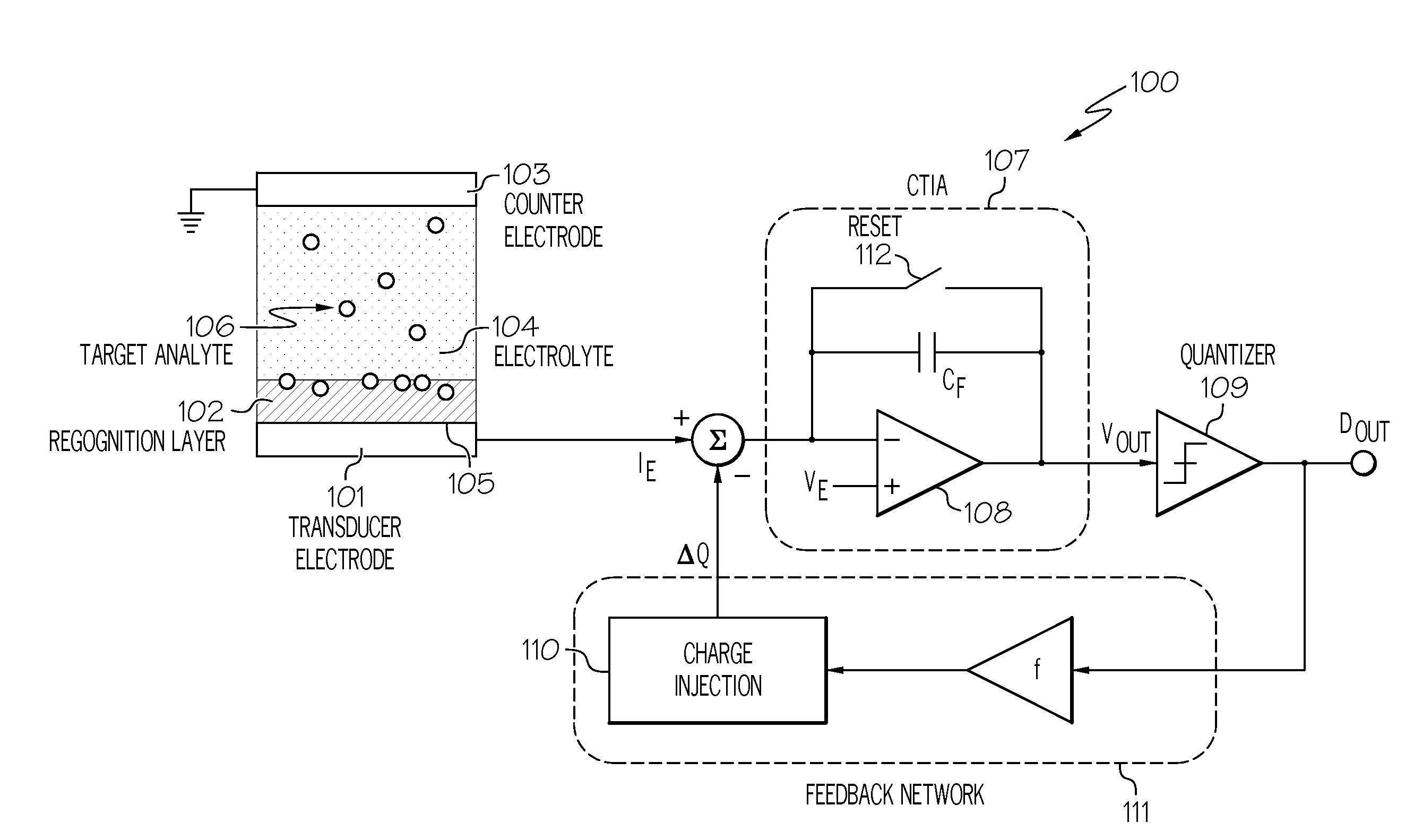
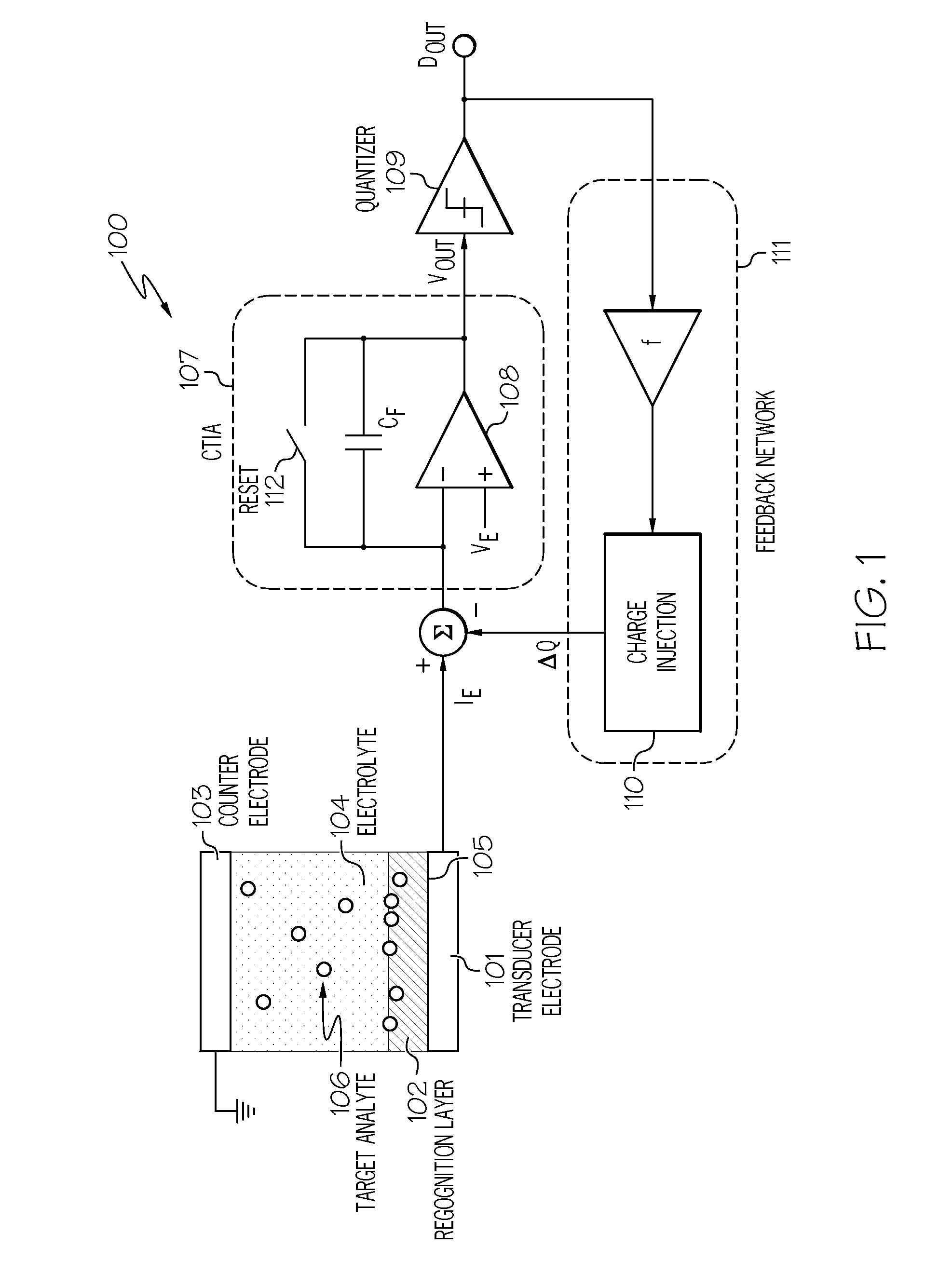
The present invention relates to a biosensor pixel and a planar two-dimensional biosensor array architecture. The biosensor pixel comprises an electrode transducer with a recognition layer, a trans-impedance amplifier, a quantizer circuit, a charge injection circuit, an in-pixel feedback network, and a 1-bit digital-to-analog converter. The biosensor array architecture comprises a plurality of biosensor pixels assembled in rows and columns, each comprising an electrode transducer, a trans-impedance amplifier, a controlled voltage source, a 1-bit comparator, and a 1-bit digital-to-analog converter. The technical effects of the invention include improved accuracy and sensitivity in measuring electrochemical interactions, reduced noise, and improved control of the current injection process.

Problems solved by technology

While electro-analytical methods are extremely versatile, they are more challenging to implement compared to their optical counterparts.
In addition, creating large scale biosensor arrays, which are imperative in biotechnology high-throughput screening applications, are very difficult, as electrically accessing individual electrodes within the array becomes the bottleneck.

Method used


Image

  • Integrated electro-analytical biosensor array
  • Integrated electro-analytical biosensor array
  • Integrated electro-analytical biosensor array

Examples


example embodiment

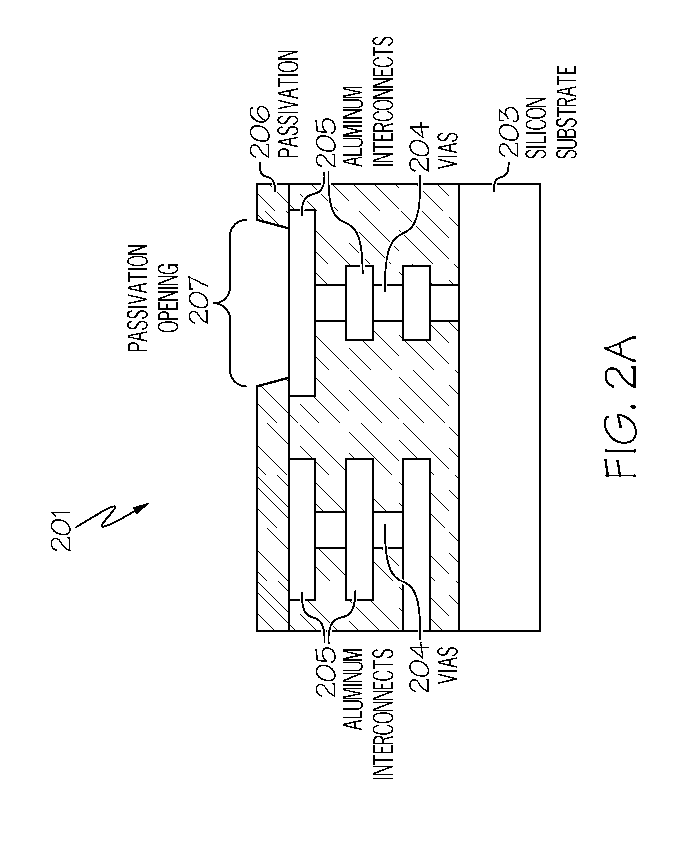
[0089]As an example embodiment, a fully-integrated electro-analytical biosensor array was fabricated using a Taiwan Semiconductor Manufacturing Company (TSMC) 0.18 μm mixed-signal CMOS process that contains 6 metal layers for interconnects on top of its silicon substrate. FIG. 8 illustrates the micrograph of this 2.5 mm×2.5 mm IC 800 in accordance with an embodiment of the present invention. Referring to FIG. 8, chip 800 includes a 12×12 array 600 of biosensing pixels 601, where each pixel 601 occupies a 120 μm×120 μm area as shown in FIG. 8.

[0090]Referring to FIG. 9, FIG. 9 is a micrograph of an individual biosensor pixel 601 in accordance with an embodiment of the present invention. Each pixel 601 in the chip includes a working electrode 701 and a Σ-Δ current detection system 901 including CTIA 107 (FIG. 4), which includes operational amplifier 108 and capacitor CF, voltage comparator 402 (FIG. 4) and the switches of 1-bit DAC 401 (FIG. 4). The reference and counter electrodes 702...


PUM

PropertyMeasurementUnit
volumeaaaaaaaaaa
electrochemical interactionsaaaaaaaaaa
currentaaaaaaaaaa

Abstract

A biosensor pixel for measuring current that flows through the electrode surface in response to electrochemical interactions and a biosensor array architecture that includes such biosensor pixels. The biosensor pixel includes an electrode transducer configured to measure a current generated by electrochemical interactions occurring at a recognition layer placed directly on top of it in response to an electrical voltage placed across an electrode transducer-electrolyte interface. The biosensor pixel further includes a trans-impedance amplifier connected to the electrode transducer, where the trans-impedance amplifier is configured to convert the current into a voltage signal as the electrochemical interactions occur. Additionally, the biosensor pixel includes a 1-bit comparator coupled to the trans-impedance amplifier and a 1-bit digital-to-analog converter coupled to the 1-bit comparator, where the 1-bit digital-to-analog converter injects different levels of charge into an input of the trans-impedance amplifier at each cycle based on an output of the 1-bit comparator.

Description

TECHNICAL FIELD[0001]The present invention relates generally to biosensors and bioelectronics, and more particularly to a biosensor pixel configured to measure the current that flows through the electrode transducer surface in response to and / or instantiated by electrochemical or biochemical interactions and a semiconductor-integrated biosensor array architecture that includes a plurality of such biosensor pixels.BACKGROUND[0002]Biosensors are devices that use biochemical reactions to identify and detect various molecules and biochemical analytes. Biosensors are widely used in different life-science applications, ranging from environmental monitoring and basic life science research to Point-of-Care (PoC) in-vitro diagnostics. Biosensors are known to be very sensitive and also extremely versatile in terms of detection. They can efficiently detect a small number of almost any type of analyte molecule or molecular structure, once a proper recognition (capturing) molecule is identified....

Claims


Application Information

Patent Timeline
Patent Type & Authority Applications(United States)
IPC IPC(8): G01N27/414
CPCG01N27/4145G01N27/4148G01N27/3277
Inventor HASSIBI, ARJANGMANICKAM, ARUNSINGH, RITURAJ
Owner BOARD OF RGT THE UNIV OF TEXAS SYST
Learn More