Optical information device, tilt detection method, computer, player, and recorder
a technology of optical information and tilt amount, which is applied in the field of optical information device and tilt amount detection method, computer, player, recorder, etc., can solve the problems of reducing reliability, increasing the size of the device, and reducing the change amount of the tilt amount of the optical information medium, so as to accurately detect reliably correct the tilt amount of the optical information medium. , the effect of reducing the amount of change of the tilt amount of the optical information
- Summary
- Abstract
- Description
- Claims
- Application Information
AI Technical Summary
Benefits of technology
Problems solved by technology
Method used
Image

Examples
first embodiment
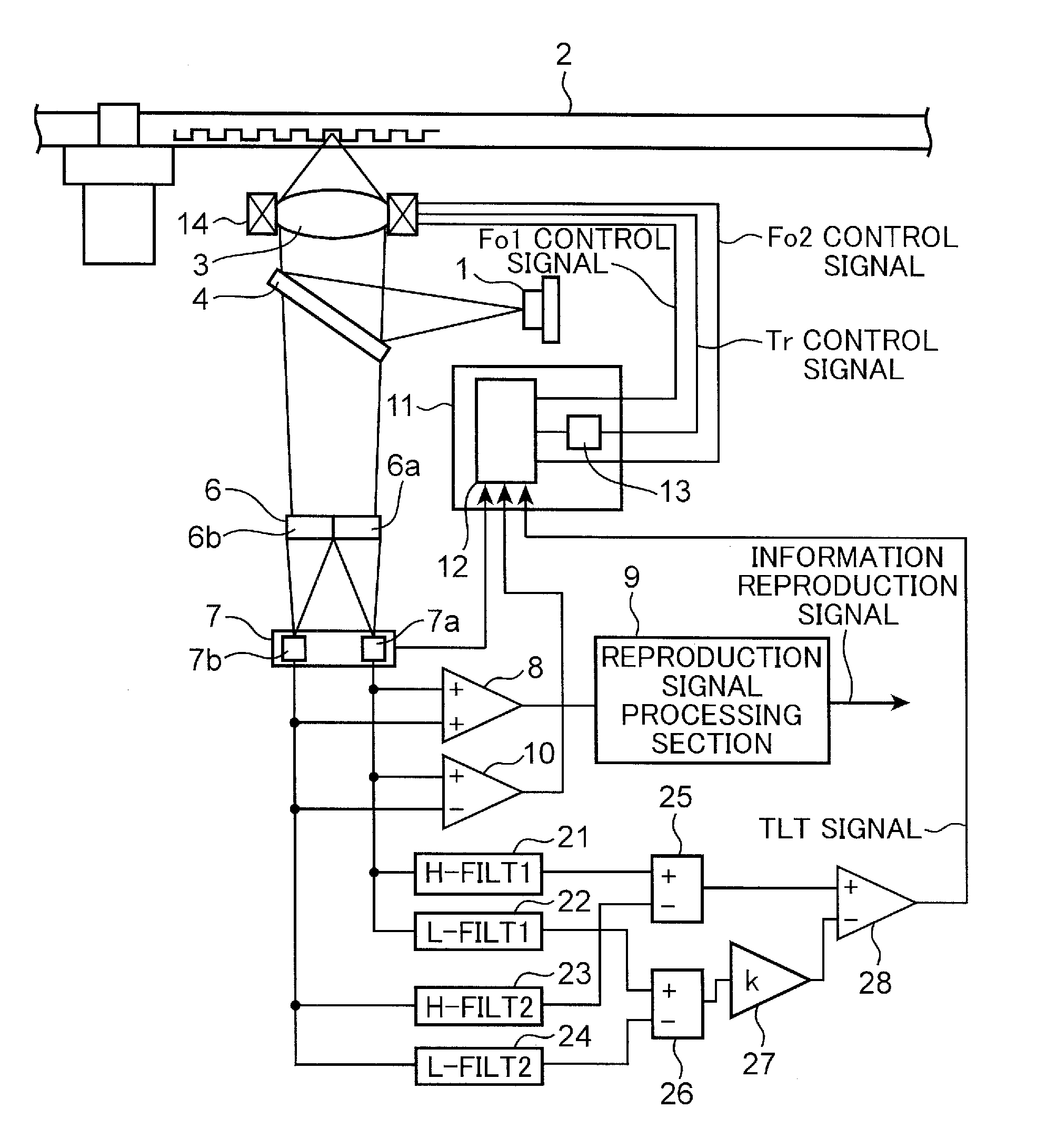
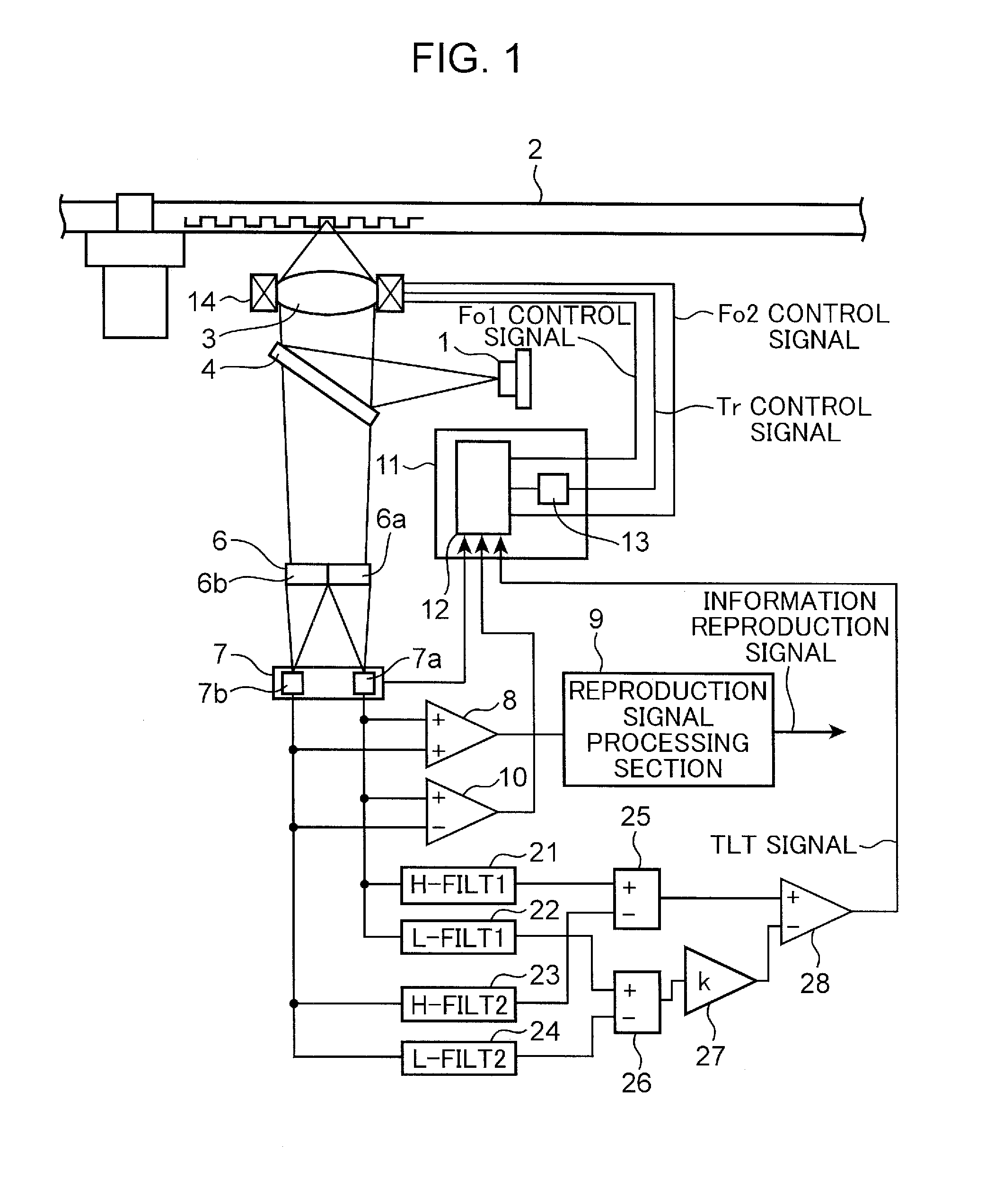
[0038]FIG. 1 is a diagrammatic view showing a configuration of an optical disc information device in a first embodiment of the present invention.
[0039]The optical disc information device shown in FIG. 1 includes a blue semiconductor laser 1, an objective lens 3, a laser mirror 4, a split element 6, a photodetector 7, an adding circuit 8, a reproduction signal processing section 9, a differential circuit 10, a control signal processing section 11, an objective lens actuator 14, a first high band extraction circuit 21, a first low band extraction circuit 22, a second high band extraction circuit 23, a second low band extraction circuit 24, a first normalization differential circuit 25, a second normalization differential circuit 26, an amplifier 27, and a differential circuit 28.
[0040]In FIG. 1, light having a wavelength of 400 nm to 415 nm is emitted from the blue semiconductor laser 1 as a laser light source. In the present first embodiment, the blue semiconductor laser 1 emits a li...
second embodiment
[0092]In a second embodiment, an example in which tilt correction and crosstalk cancel are combined will be described. Note that components which are the same as those in the first embodiment are designated by the same reference numerals, and the detailed description thereof will be omitted.
[0093]FIG. 14 is a diagrammatic view showing the configuration of the optical disc information device of the second embodiment of the present invention. The second embodiment is different from the first embodiment in that a split element 60 split into three portions is used in place of the split element 6 split into two portions.
[0094]The optical disc information device shown in FIG. 14 includes the blue semiconductor laser 1, the objective lens 3, the laser mirror 4, the split element 60, a photodetector 70, the adding circuit 8, the reproduction signal processing section 9, the differential circuit 10, the control signal processing section 11, the objective lens actuator 14, the first high band...
third embodiment
[0113]A computer according to a third embodiment includes the optical disc information device according to the first embodiment or the second embodiment.
[0114]FIG. 19 is a perspective view showing the schematic configuration of the computer according to the third embodiment of the present invention.
[0115]A computer 609 shown in FIG. 19 includes an optical disc information device 607 according to the first embodiment or the second embodiment, an input device 616 such as a keyboard 611 or a mouse 612 for inputting information, an arithmetic unit 608 such as a central processing unit (CPU) that performs an arithmetic operation based on information inputted from the input device 616 and information read from the optical disc information device 607, and an output device 610 such as a cathode-ray tube or a liquid crystal display device that displays information such as the result of the arithmetic operation of the arithmetic unit 608 or the like.
[0116]The computer 609 according to the pre...
PUM
| Property | Measurement | Unit |
|---|---|---|
| wavelength | aaaaa | aaaaa |
| wavelength | aaaaa | aaaaa |
| length | aaaaa | aaaaa |
Abstract
Description
Claims
Application Information
 - R&D
- Intellectual Property
- Life Sciences
- Materials
- Tech Scout
- Unparalleled Data Quality
- Higher Quality Content
- 60% Fewer Hallucinations
Browse by: Latest US Patents, China's latest patents, Technical Efficacy Thesaurus, Application Domain, Technology Topic, Popular Technical Reports.
© 2025 PatSnap. All rights reserved.Legal|Privacy policy|Modern Slavery Act Transparency Statement|Sitemap|About US| Contact US: help@patsnap.com