Subject placement and head positioning device

a head positioning and subject technology, applied in the field of patient placement, can solve the problems of poor image quality in comparison to coils that are in close proximity to the voi, reduce the sensitivity of the process, so as to reduce the stress on the wrist, reduce the lifting angle of the board, and facilitate the effect of tilting and sliding

Inactive Publication Date: 2014-10-30
XLR IMAGING
View PDF1 Cites 10 Cited by
  • Summary
  • Abstract
  • Description
  • Claims
  • Application Information

AI Technical Summary

Benefits of technology

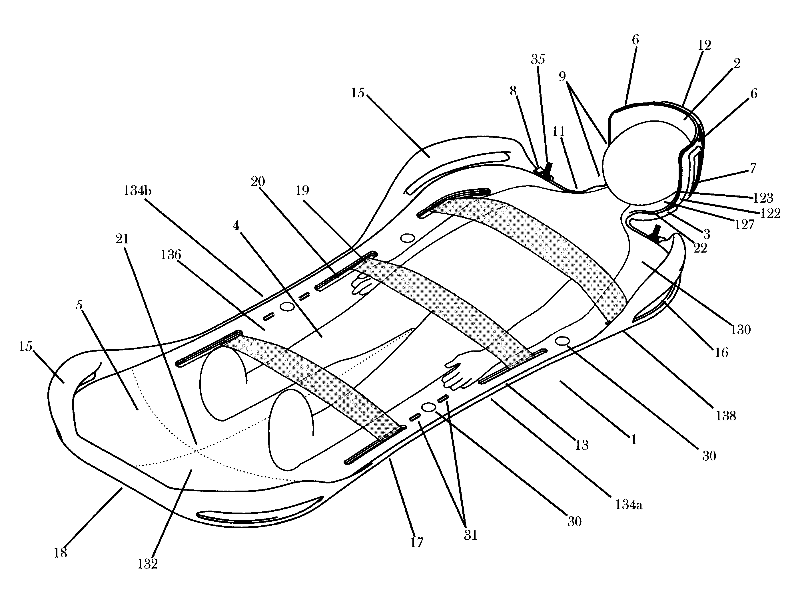
[0038]The present invention provides for a patient placement device for use in a diagnostic imaging and / or therapeutic, such as oncological, treatment setting. The invention is a device that may be easily adjusted to accommodate variations in head size and still allow for consistent and accurate patient placement or centering. The current invention may also facilitate the placement of subjects (both compliant and non-compliant) from preparation areas into the diagnostic imaging or oncology system thereby potentially saving time and resources. One particular, but not exclusive, area of diagnostic imaging for the present invention is in neurological applications, where placement of the head is critical. One embodiment of the present invention is particularly suited to the unique requirements of pediatric diagnostic medical imaging in all modalities, and serves several of the functions outlined in the prior art, with a focus on addressing the additional, unique and demanding needs of Pediatric MR Imaging described below.
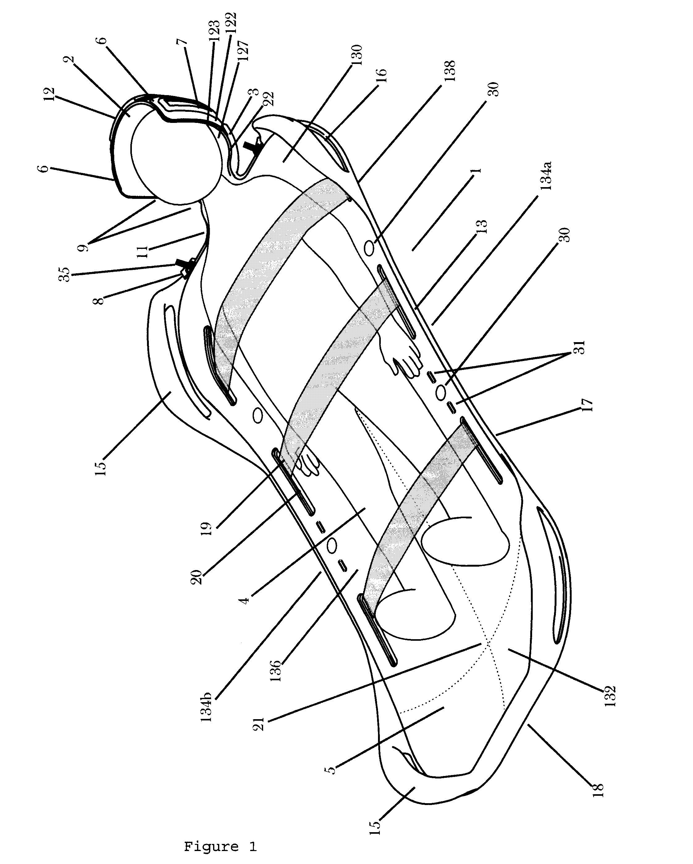
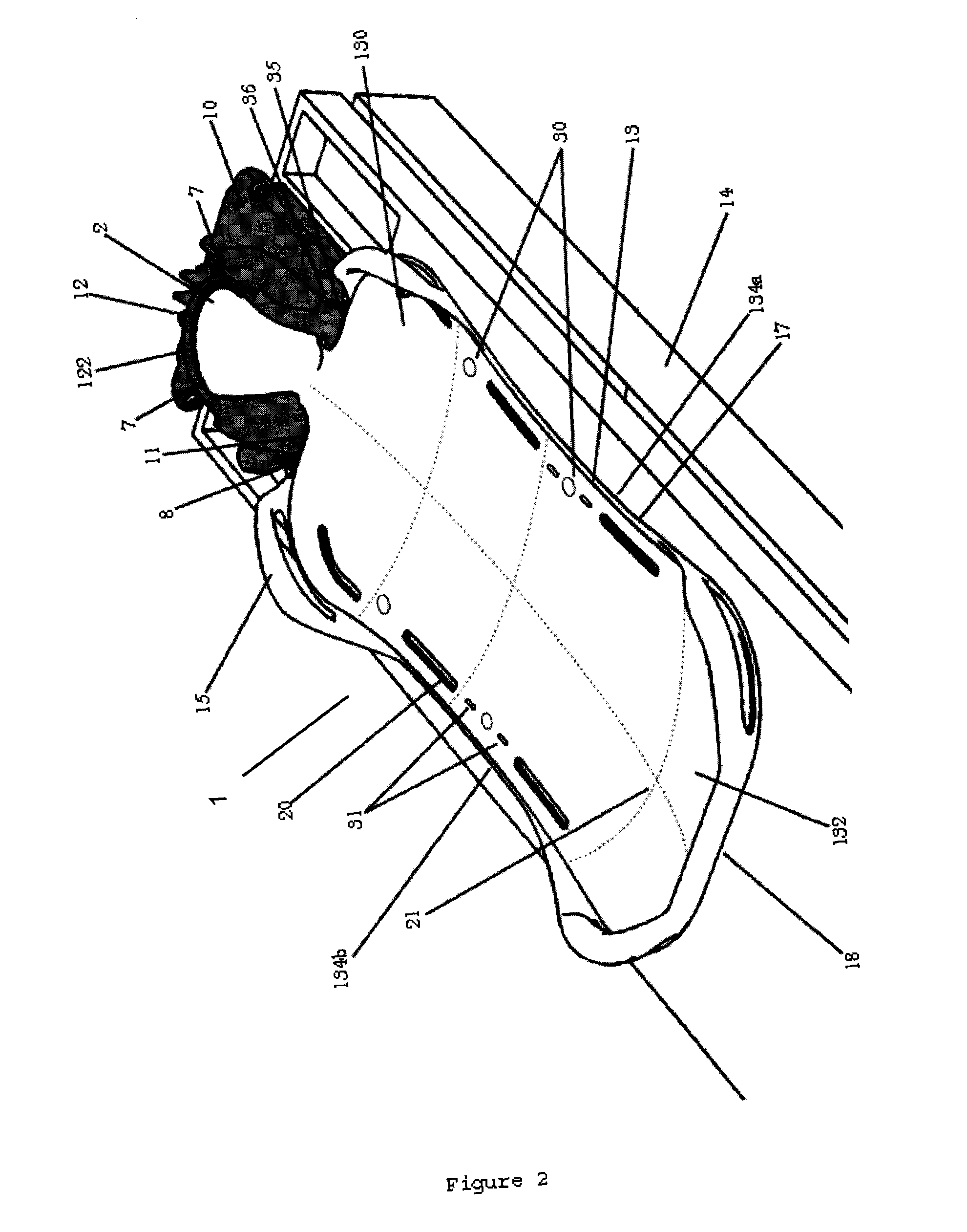
[0039]Exemplary embodiments of the invention include a patient table compatible board or placement device including an integrated or interchangeable head and neck cradle that provides clearance for other medical equipment and is divided into flexible sections or flaps that adjust to accommodate a range of head diameters, an integrated user-adjustable head motion reduction system for centering a patients head in the iso-center of a desired location using the flexible sections, and geometry and locator tabs that couple the board to particular shapes and imaging or therapeutic systems for providing a consistent and repeatable position of the patient.
[0040]Further exemplary embodiments of the invention include a head motion reduction and control system including a spring-loaded member that displaces the flexible sections of the head cradle and can be hidden from view, an actuation system with tactile feedback and limited range to eliminate the risk of over tensioning that routes the motion for this member via a cable and housing, through an integrated slot that obscures its function from view, and a control system that can be coupled to the imaging or therapeutic system and that releases in the event of an emergency.
[0041]Further exemplary embodiments of the invention include a method of positioning a compliant or non-compliant patient on the board, including integrated straps on the board for minimizing motion of the body below the chest, a defined curvature across the width and length of the board, and a conformal inner geometry within the head and neck cradle for automatically centering a patient's body and occipital section of the head along the central plane of the board.
[0042]Further exemplary embodiments of the invention include aids for transferring a patient to an imaging or therapeutic system, including a conformal shaped head and neck cradle for supporting the neck and head during insertion or extraction, a lip or raised edge to allow for easy tilting and sliding of the board from a gurney or other system, a flat base for limiting the lift angle of the board and integrated, interchangeable, and curved handles to minimize stress on wrists when moving the board.

Problems solved by technology

This procedure is often a time consuming and iterative process, particularly for applications where: wide variations in subject size are common, the patient is non-compliant, sedated or anesthetized, and / or the patient needs to be prepared outside of the exam room.
The large distance from the MRI volume of interest (VOI) to the “stock” RF body coil (in the magnet bore) decreases their sensitivity and as a result, creates poor images in comparison to coils that are in close proximity to the VOI.
Patient comfort and ease of patient placement and removal from conformal RF coils is an issue for the preparatory setup required for human subject MRI scans.
Furthermore, due to the nature of how MR images are obtained, the reduction of motion of subjects is critical to ensure high quality MR images, and this problem can be a particular issue with conformal coils that do not fit the patient tightly.
Unfortunately, pediatric use can exacerbate the preparatory and motion problems of MR imaging (and indeed other modalities) in general and specifically when done using conformal coils.
MRI scans involve a significant use of time and resources to obtain clinically relevant diagnostic images, typically 30 to 60 minutes, and require patients / subjects to lie still for the entire exam, which is difficult for young children to comply with, particularly for infants and children under the age of 6 years.
As a result, current practice at pediatric hospitals and imaging centers involves the administration of sedatives or anesthetics to children, which greatly increases the risk to patients, the total exam time required, and the cost of the MRI exam.
Unfortunately, the conformal nature of these coils presents challenges in placing and removing a subject's head, due to the limited space between the coil and head.
The current practice to address this issue is to use improvised solutions and oversized coils, which take additional time and reduce the potential savings that would accrue from using appropriately sized RF head coils for the child.
In pediatric imaging, and in particular MR imaging, a child that is sedated or anesthetized (non-compliant) adds additional difficulties, including: in head positioning and placement m conformal coils; in transferring the child from a preparatory room / gurney to the imaging system; and in removing the subject from the conformal coils.
Disadvantages of the positioners and head cradles of the prior art disclosures include; (1) they are too cumbersome and invasive; (2) involve patient compliance which is not possible with children; (3) require relatively long time to set up and to use (a particular disadvantage for child patients); (4) cannot handle the variation in head sizes present in the general population and children; and (5) have mechanisms that are too visible to children (appearance has an impact on function since it affects acceptance from young children, which affects sedation use.

Method used


Image

  • Subject placement and head positioning device
  • Subject placement and head positioning device
  • Subject placement and head positioning device

Examples


Embodiment Construction

[0091]In this specification and in the claims that follow, reference will be made to a number of terms that shall be defined to have the meanings below. All numerical designations, e.g., dimensions and weight, including ranges, are approximations that typically may be varied (+) or (−) by increments of 0.1, 1.0, or 10.0, as appropriate. All numerical designations may be understood as preceded by the term “about”.

[0092]The singular form “a”, “an”, and “the” includes plural references unless the context clearly dictates otherwise.

[0093]The term “comprising” means any recited elements are necessarily included and other elements may optionally be included. “Consisting essentially of” means any recited elements are necessarily included, elements that would materially affect the basic and novel characteristics of the listed elements are excluded, and other elements may optionally be included. “Consisting of” means that all elements other than those listed are excluded. Embodiments defined...


PUM


Abstract

The present invention relates to a subject placement device for use in a diagnostic and / or therapeutical treatment setting. The subject placement device of the present invention includes: (a) a board for receiving a body of the subject, and (b) a head cradle extending from said board, said head cradle being enabled to receive a range of head diameters.

Description

CROSS-REFERENCE TO RELATED APPLICATION [0001]This application claims priority to U.S. provisional application No. 61 / 563,709 filed on Nov. 25, 2011, which is incorporated herein in its entirety by reference.FIELD OF THE INVENTION [0002]The present invention relates generally to patient placement in a medical diagnostic and / or treatment setting and, more specifically, to a patient placement device having a head cradle that reduces head motion and allows for accurate, repeatable head position centering when used in diagnostic imaging or radiation oncology applications.BACKGROUND OF THE INVENTION[0003]Diagnostic imaging, which may include magnetic resonance imaging (MRI), computed tomography (CT), positron emission tomography (PET), or X-rays, and radiation oncology require accurate and consistent placement of anatomical regions of interest for patients of various ages and sizes relative to a desired volume, which is defined by a three dimensional imaging field of view or radiation tar...

Claims


Application Information

Patent Timeline
Patent Type & Authority Applications(United States)
IPC IPC(8): A61B5/055A61G13/12
CPCA61G13/121A61B5/0555A61B6/032A61B6/037A61B6/0428A61B2503/06A61B2503/40A61B5/702A61B5/704A61B5/055
Inventor BARBERI, ENZO ANTONIOKERR, JOSEPH ROBERT
Owner XLR IMAGING
Why Eureka
Try Eureka