Multiplexed fiber optic sensing system and method

a fiber optic and sensing system technology, applied in the field of multi-channel fiber optic sensing systems and methods, can solve the problems of optical fiber-based sensing systems, channel count, and the inability to use more than a handful of optical sensing channels, and achieve the effect of increasing bandwidth

Active Publication Date: 2014-11-06
HALLIBURTON ENERGY SERVICES INC
View PDF5 Cites 17 Cited by
  • Summary
  • Abstract
  • Description
  • Claims
  • Application Information

AI Technical Summary

Benefits of technology

[0006]In one example, the optical sensors include Fabry-Perot interferometer structures operated in a transmission mode. In such sensors, an acceleration, or acoustic or mechanical vibrational energy, can be coupled to a respective interferometer structure to adjust (e.g., modulate) a transmission characteristic of the interferometer structure, such as adjusting one or more of a transmitted wavelength of optical energy, or a phase of the transmitted optical energy. Such adjusted optical energy transmitted through respective interferometer structures can be coupled to an optical demodulator, and information indicative of the acceleration, or acoustic or mechanical vibration can be obtained. Wavelength division multiplexing (WDM) may be provided by specifying respective geometries of respective interferometer structures to provide staggered transmission wavelengths corresponding to respective sensors.
[0007]An available dynamic range of acoustic or mechanical sensing for a particular interferometric sensor may be established by an available range of mechanical displacement of one or more portions of the sensor. Such mechanical displacement establishes the range of wavelength deviation or phase deviation provided to an optical signal transmitted through the sensor. Generally, an optical source bandwidth (e.g., an available range of wavelengths) from the source is selected to provide a range of wavelengths about the same as or wider than a range of wavelength deviation provided by a respective interferometric sensor.
[0008]Time division multiplexing (TDM) may be provided by controlling delivery of respective instances of optical energy (e.g., optical pulses) to respective interferometer structures. For example, one or more of an optical switch or an optical delay line can be used, such as to delay, inhibit, or provide delivery of optical energy to respective sensors in a specified temporal order. And further in some examples, signals from such sensors will be communicated and processed through use of both TDM and WDM.
[0009]In some examples, a broadband source is used to provide pulses of broadband light for communication to an array of such sensors; and in some examples this broadband source includes a plurality of emitters that are pulsed simultaneously, with the emitted light combined to form a light pulse of relatively increased bandwidth relative to that of each emitter.

Problems solved by technology

One issue facing some optical fiber-based sensing systems is channel count.
However, such an approach may preclude use of more than a handful of optical sensing channels, because the number of optical fibers or channels may be limited due to cost or space constraints.
For example, in a downhole application, a cross-sectional area available for optical fiber assemblies may be limited, and interconnect complexity between respective fibers and other portions of the sensing system may preclude large channel counts without compromising reliability.

Method used


Image

  • Multiplexed fiber optic sensing system and method
  • Multiplexed fiber optic sensing system and method
  • Multiplexed fiber optic sensing system and method

Examples


example 1

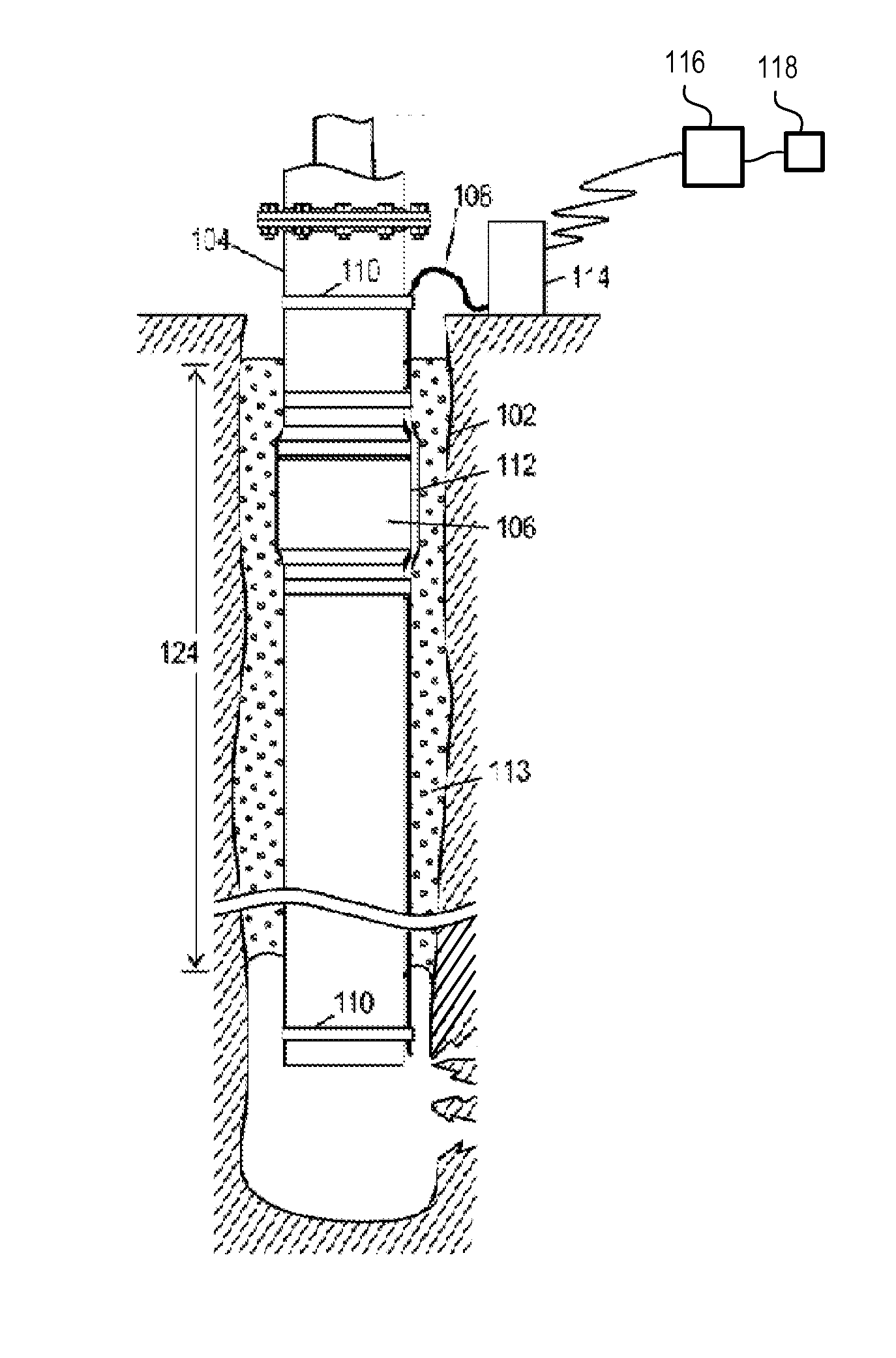
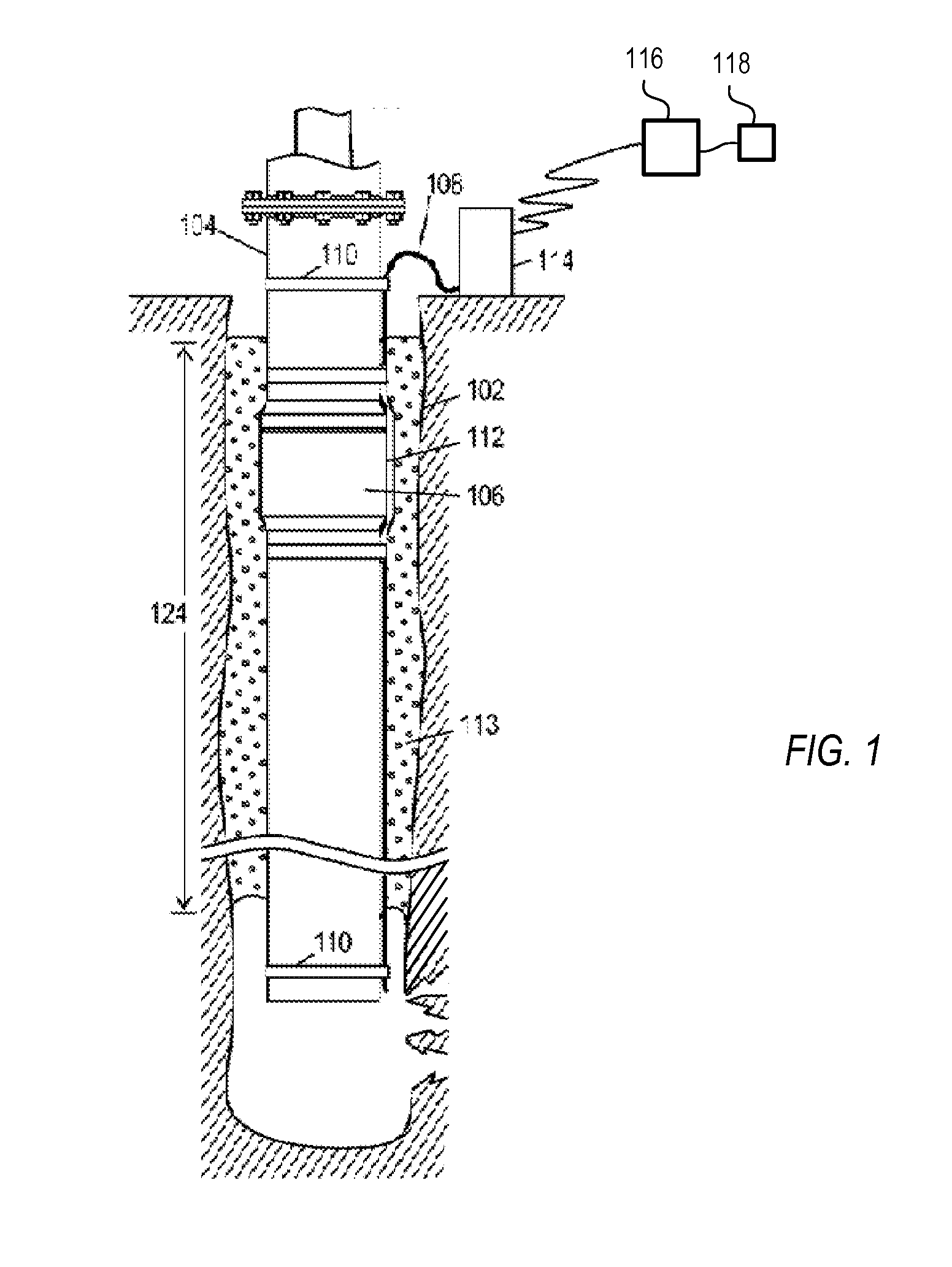
[0089]FIG. 8 is a schematic drawing of a first example interrogation module 800, which includes a single Michelson interferometer 806 that converts a wavelength shift to a phase shift, followed by a CWDM 818 to separate the four data channels from one another, followed by a 4-by-N channel WDM / TDM demodulator 820 that converts a phase shift to an intensity that is detectable on a detector, and also matches a sensed set of spectra with the proper sensor. In some examples, as depicted in FIG. 1, the interrogation module, as well as the light source, may be considered as a part of the processing assembly 114.

[0090]In this example interrogation module 800, the output fiber 726 delivers pulsed light having a spectrum that may be analyzed to extract data sensed from a corresponding sensor. The spectrum has four peaks, where the peak wavelength of each peak is indicative of a sensed acceleration value. The pulses are delivered to an amplifier 804. An example of a suitable amplifier 804 is a...

example 2

[0098]FIG. 9 is a schematic drawing of a second example interrogation module 900, which includes a CWDM 906 to separate the four data channels from one another, followed by four Michelson interferometers 908, 910, 912, 914 that each converts a wavelength shift to a phase shift, followed by a 4-by-N channel WDM / TDM demodulator 820 that converts a phase shift to an intensity that is detectable on a detector, and also matches a sensed set of spectra with the proper sensor.

[0099]In this example interrogation module 900, the output fiber 726 delivers pulsed light to an amplifier 904. The amplified pulses from the optical amplifier 904 pass through a CWDM 906, which separates them into the four data channels X, Y, Z, H. Light in each of the four data channels is directed to its own Michelson interferometer 908, 910, 912, 914. Each Michelson includes first and second paths, as described above, with the second path in each including a PZT-base modulator 924, 926, 928, 930. These four modula...

example 3

[0102]FIG. 10 is a schematic drawing of a third example interrogation module 1000, which includes a 3-by-3 coupler 1006 that couples light into and out of a Michelson interferometer that converts a wavelength shift to a phase shift, the 3-by-3 having three outputs, each of which is directed into a respective CWDM 1016, 1018, 1020 that separates the four data channels from one another, followed by four 1-by-N channel WDM / TDM demodulators 1024, 1026, 1028, 1030 that convert a phase shift to an intensity that is detectable on a detector, and also match a sensed set of spectra with the proper sensor. Note that the four 1-by-N WDM / TDM demodulators are functionally equivalent to the single 4-by-N WDM / TDM demodulator discussed above.

[0103]In this example interrogation module 1000, the output fiber 726 delivers pulsed light to a first port of a circulator 1004. The pulses exit through a second port of the circulator 1004 and are directed toward one of three input ports in a 3-by-3 coupler 1...


PUM


Abstract

A sensing system includes plurality of sensors along the lengths of input and output optical fibers. Each sensor receives broadband pulses from the input fiber, dynamically senses a plurality of physical parameters in a one-to-one correspondence with a plurality of predefined wavelength bands, and forms signal pulses from the broadband pulses by transmitting only a single wavelength within each wavelength band. Each single wavelength has a dynamically-varying peak wavelength value indicative of the corresponding sensed physical parameter. The signal pulses from the output optical fiber are directed into one or more interferometers, which produce a phase deviation corresponding to each dynamically-varying peak wavelength value.

Description

BACKGROUND[0001]The present invention relates generally to methods and apparatus for distributed optical sensing of acoustic or mechanical energy, and more particularly relates to systems and methods using a sensing system including a plurality of sensors coupled to one or more optical fibers, and also to a broadband pulsed light source suitable for use in such a system.[0002]Systems that sense acoustic or mechanical energy are used in a variety of applications, including, but not limited to, oilfield drilling and maintenance, underwater monitoring, and maintenance of large structures, such as mines, bridges and elevators. In these sensing systems, sensors take measurements at their respective locations. The measurements taken by the sensors are compiled and may be used to provide information regarding the structure(s) or locations that are monitored.[0003]One class of sensor is optical in nature. An optical sensor can generate optical signals, and can direct the measured informatio...

Claims


Application Information

Patent Timeline
Patent Type & Authority Applications(United States)
IPC IPC(8): G01J1/04
CPCG01J1/0425G01D5/35306G01D5/35335G01D5/35387G01H9/004G01P15/093G01P15/18
Inventor CHOI, HAN-SUNSAMSON, ETIENNE
Owner HALLIBURTON ENERGY SERVICES INC
Why Eureka
Try Eureka