Gas turbine combined cycle system

a combined cycle and gas turbine technology, applied in steam engine plants, machines/engines, mechanical equipment, etc., can solve the problems of limiting the effect of higher firing temperature, air affecting gas turbine performance, and air used to cool the stage 1 rotor not producing useful shaft work

Inactive Publication Date: 2014-11-13
BECHTEL POWER CORP
View PDF13 Cites 17 Cited by
  • Summary
  • Abstract
  • Description
  • Claims
  • Application Information

AI Technical Summary

Benefits of technology

[0040]Among other control objects, the controller is arranged to provide a high turbine inlet temperature at the first power block, for power g

Problems solved by technology

The design of high efficiency, high temperature gas turbines presents challenges including (1) cooling of the turbine hot gas path (HGP) components operating at such high temperatures; and (2) control of NOx and CO emissions.
Turbine HGP cooling by compressor extraction air is detrimental to gas turbine performance in at least two aspects.
Thus, in order to achieve a desired firing temperature, the gas turbine combustor needs to be fired that much harder, with direct impact on NOx emissions.
Another aspect of air cooling is that the air used to cool the stage 1 rotor does not produce useful shaft work.
The cooling air limits the desired impact of higher firing temperatures.
Such developments remain a major challenge.
But commercialization seems to be decades off.
One drawback of steam c

Method used


Image

  • Gas turbine combined cycle system
  • Gas turbine combined cycle system

Examples


Embodiment Construction

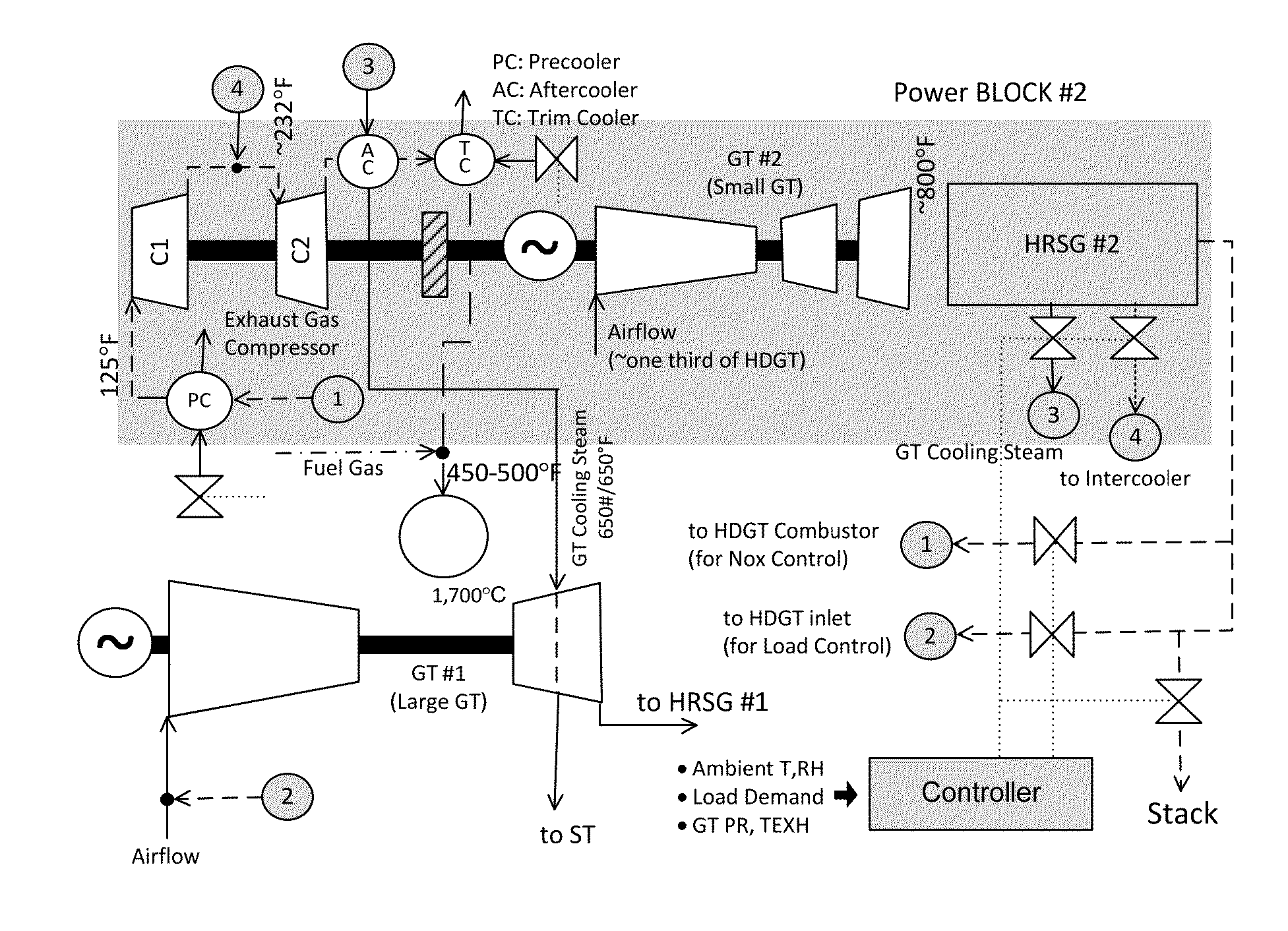
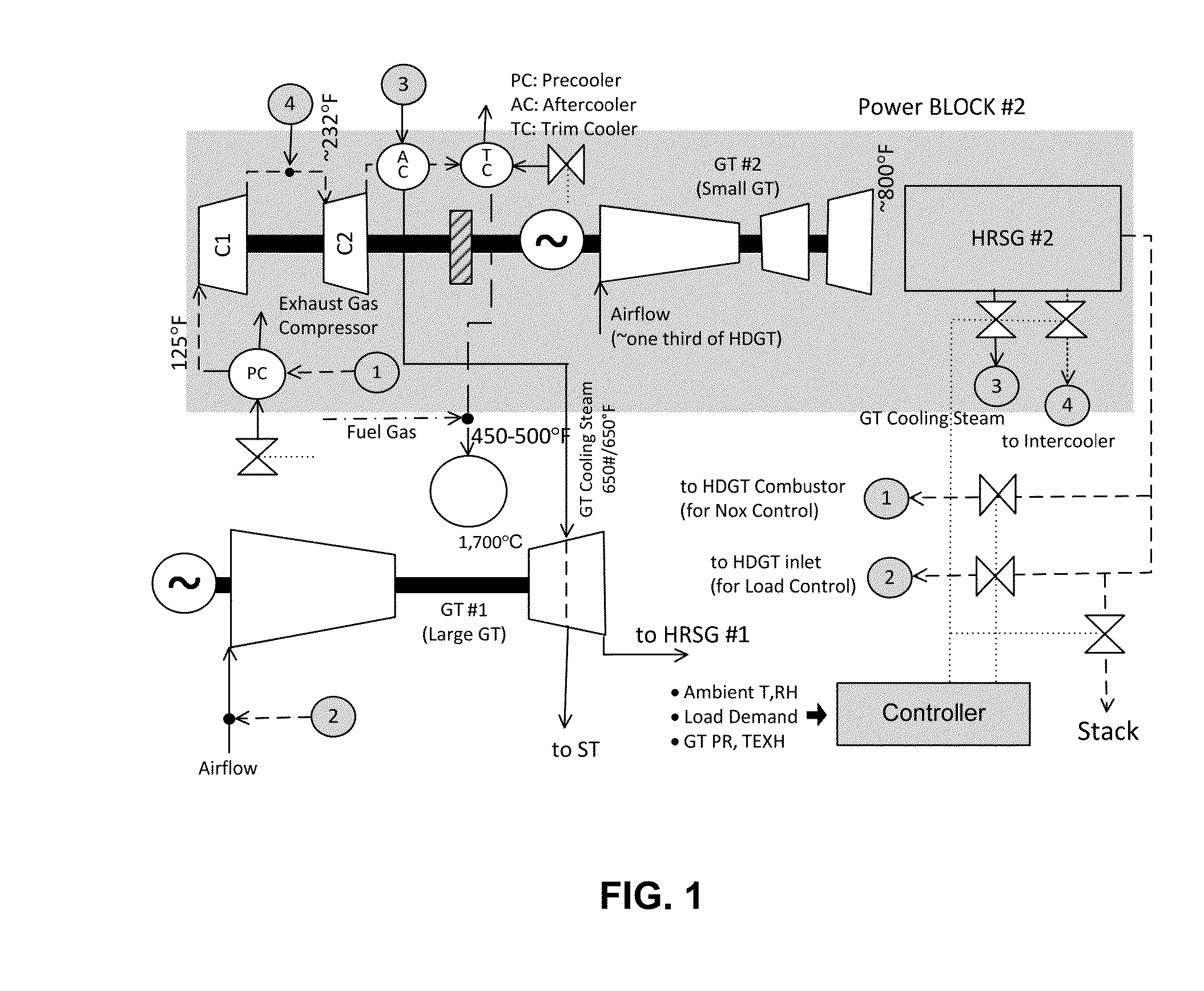
[0043]An exemplary embodiment as shown in FIG. 1 has two power blocks. Power Block 1 comprises a first gas turbine (GT #1) and a steam turbine (ST), labeled but not shown as a separate block, on a single shaft driving a single generator or each driving its own generator in a multi-shaft configuration. Power Block 2 comprises a second gas turbine (GT #2) and an intercooled, two-stage flue gas compressor (FGC) on a single shaft with a single electric generator.

[0044]The gas turbine prime mover of each power block burns fuel and is thermally coupled to a heat recovery steam generator HRSG via the exhaust of the respective prime mover, i.e., GT #1 supplies hot exhaust gas to HRSG #1 (labeled but not shown as a separate block) and GT #2 supplies hot exhaust gas to HRSG #2.

[0045]The shaft configuration of Power Block 2 is not critical to the invention. That is, Power Block 2 can be a single-shaft or multi-shaft configuration. In a multi-shaft configuration, the FGC can be driven by an ele...


PUM


Abstract

In a combined cycle gas turbine configuration having at least two power blocks, stack emissions (particularly nitrous oxides or NOx but also carbon monoxide CO and unburned hydrocarbons, UHC) are controlled concurrently with part load power output. In one power block a combined cycle power plant has a relatively large heavy-duty industrial gas turbine fired to about 1,700° C. at the turbine inlet leading to a first heat recovery system. A second power block with a smaller gas turbine has a second heat recovery system. A controller adjusts coupling of flue gas and steam paths from the second power block to the first power block to meet load demand in compliance with applicable emissions regulations.

Description

CROSS-REFERENCE TO RELATED APPLICATION[0001]This application claims the benefit of U.S. Provisional Application No. 61 / 820,901, filed May 8, 2013.FIELD[0002]This disclosure concerns the field of gas turbines and in particular provides methods and apparatus for managing stack emissions (e.g., nitrous oxides (NOx), carbon monoxide (CO), unburned hydrocarbons (UHC) and the like), while concurrently controlling load power output. The invention is particularly applicable to combined cycle power plants with heavy-duty industrial gas turbines, fired, for example, to 1,700° C. (3,092° F.) at the turbine inlet.BACKGROUND[0003]The term “combined cycle” generally refers to an assembly of two or more engines driven from the same source of heat, converting heat energy into mechanical energy, usually to drive one or more electrical generators. In gas turbine (GT) combined cycle plants, expansion of product gas resulting from combustion of fuel turns a gas turbine. Hot exhaust gases from the gas t...

Claims


Application Information

Patent Timeline
IPC IPC(8): F01K23/10
CPCF01K23/10Y02E20/16F01K23/101
Inventor GULEN, SEYFETTIN C.
Owner BECHTEL POWER CORP
Why Eureka
Try Eureka